Tube walker for examination and repair of steam generators

a technology of steam generators and tubes, applied in vehicle heating/cooling devices, transportation and packaging, light and heating apparatus, etc., can solve the problems of increasing the difficulty of manual steam generator repair, inability to control computer control, and inaccessible parts, so as to reduce the time required to move the manipulator, eliminate any variation in the moving time, and move efficiently and consistently

Active Publication Date: 2009-05-19
AREVA NP INC
View PDF19 Cites 6 Cited by
  • Summary
  • Abstract
  • Description
  • Claims
  • Application Information

AI Technical Summary

Benefits of technology

[0013]The present invention solves these problems of the prior art manipulators and others by providing a system to remotely relocate the above described manipulator with minimal support from personnel on the work platform during reactor shut down. This takes away the need for highly experienced support for manually moving the manipulator. The tube walker of the present invention consists of a movable system for reciprocally moving a body connected to the manipulator having a movable inner section and an outboard section. Both the inner and outboard sections have groups of 4 hydraulically actuated locking fingers which engage the tubes of the steam generator tube bundle. When the 4 fingers of the outboard section are locked in place, the fingers of the inner section are disengaged and the inner portion can be moved axially to an aligned position with new tube locations. Then the inner portion can be locked in place to tubes of the new location and the 4 outboard fingers can be disengaged. This allows the outboard section to be moved to a new tube location. This combination of reciprocal motion allows the walker to traverse in a straight line from one side of the generator tube bundle to the other side and back. The manipulator is attached to the walker using a pneumatic coupler.
[0014]From the foregoing it will be seen that there are two advantages with this system. The first is decreased time required to move the manipulator. The manipulator can efficiently and consistently be moved in a time comparable to that of the best moves done remotely by an individual. This system also eliminates any variation in that moving time. The second advantage is less radiation dose received by the support personnel. The need for an individual to be standing at the manway to move the manipulator no longer exists. This results in significant dose savings over the duration of an outage.
[0015]In view of the above it will be seen that one aspect of the present invention is to provide a system for easily moving the manipulator across the row of steam generator tubes from a remote location.
[0016]Another aspect is to provide a speedy movement of the manipulator to minimize radiation exposure of the personnel during reactor down time.

Problems solved by technology

However, nuclear systems are unique in that many components are inaccessible, due to the radiation levels.
As maintenance activities and radiation levels increased, it became increasingly difficult to perform steam generator repairs manually.
Although also manually installed, it was not computer controlled.
Both manipulators performed well for inspection, but they could not support the heavy tools required for plugging and other tube repair operations.
1. must be installed with no human entry in the steam generator,
2. must perform inspection and repair duties,
3. must access all tubes, and
4. must be computer controlled.One of the remote manipulator designs is shown in FIG. 1. Named ROGER® (Remotely Operated Generator Examination and Repair); it is covered by U.S. Pat. No. 4,804,038 and was placed in service in the mid nineteen eighties. The unit is installed in the steam generator head by a series of cables and pulleys as shown in FIG. 2. Although light weight in construction, it has a load capacity of 200 lb (91 kg). Once calibrated, the toolhead can be remotely moved to any tube location within the region it was installed with the exception of the mounting location, or “exclusion zone”. With the exception of tool head installations, all operations are remotely controlled and monitored by video equipment. The control station is located outside of the containment building and control signals are often multiplexed to reduce the number of cables that must be routed to the building.One problem was that the manipulator had to be manually moved to different regions within the steam generator. This allows access to the tubes that were in the exclusion zones. Personnel expended time and dose exposure to relocate the manipulator to the desired region. This was especially a problem when personnel were not very experienced.

Method used


Image

  • Tube walker for examination and repair of steam generators
  • Tube walker for examination and repair of steam generators
  • Tube walker for examination and repair of steam generators

Examples


Embodiment Construction

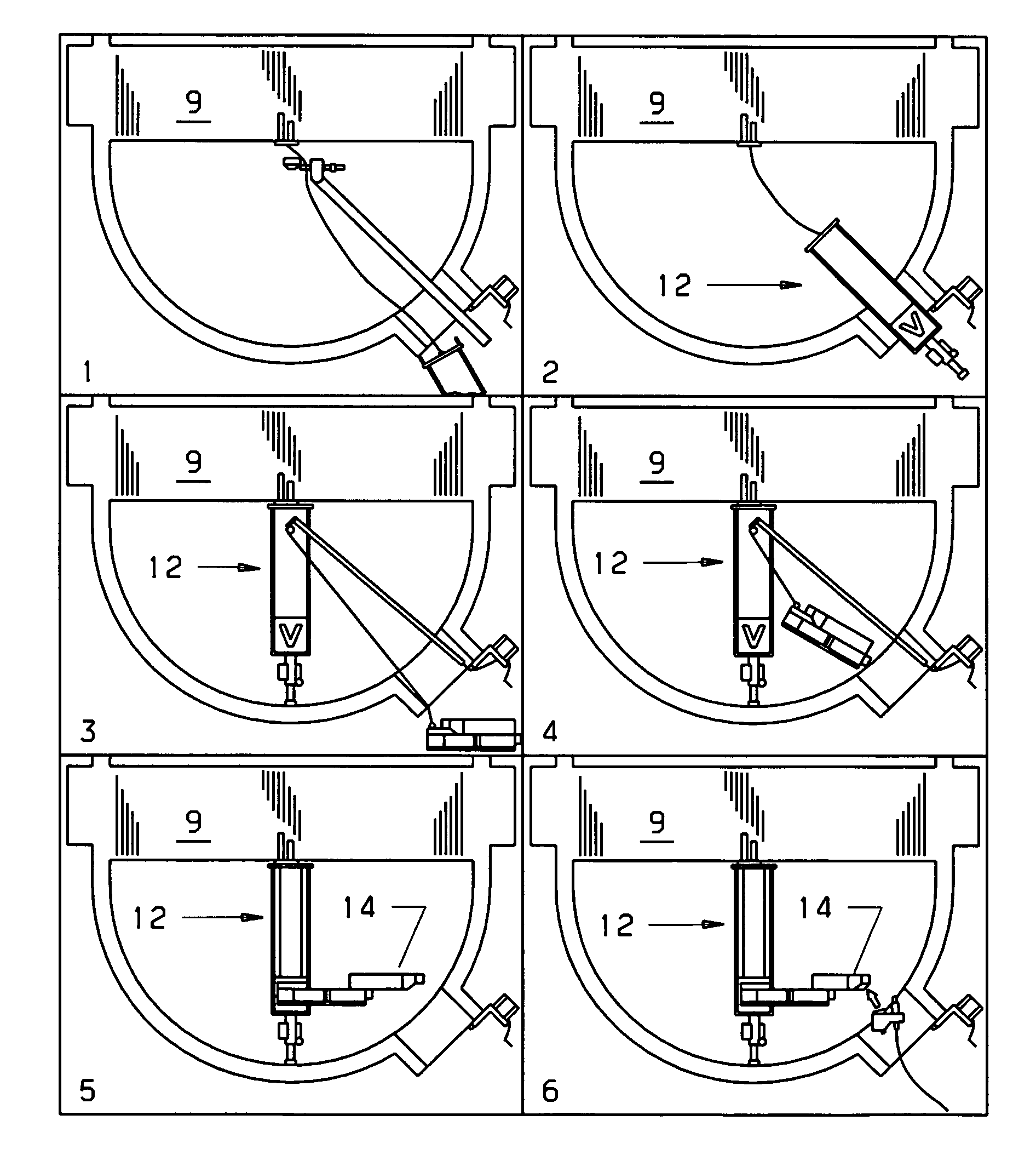
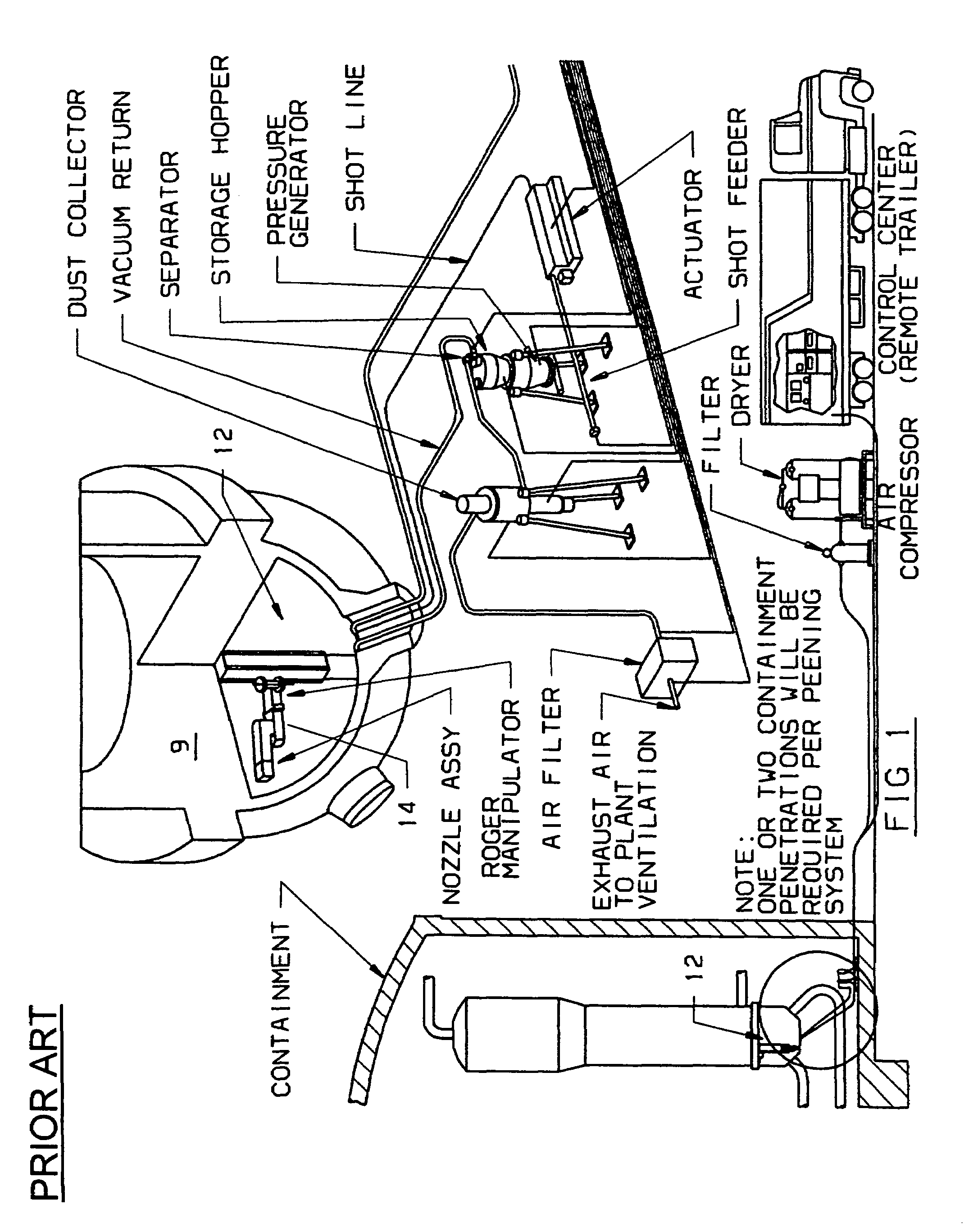
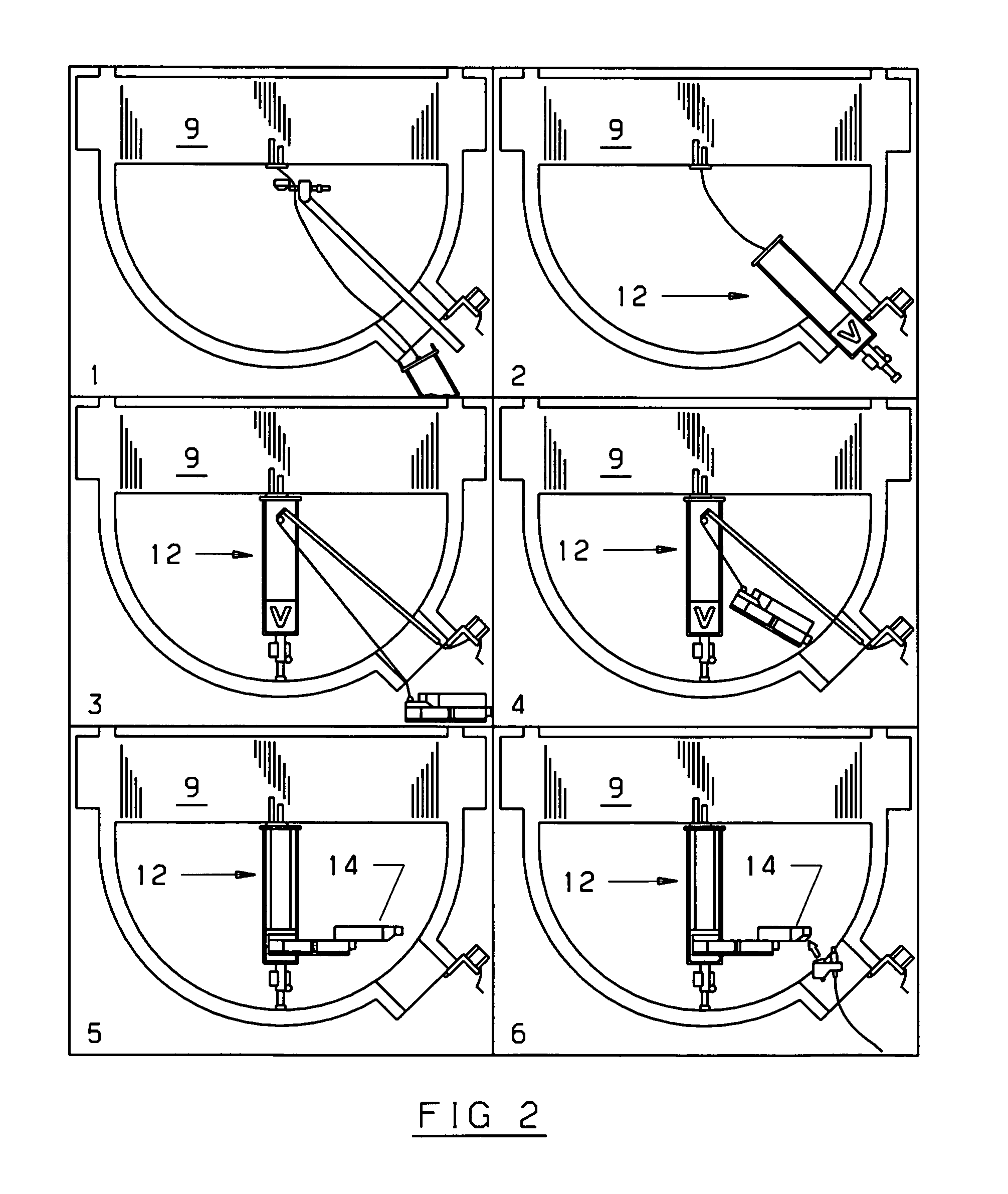
[0025]Referring now to the drawings and particularly to FIGS. 3 and 4, an improved manipulator system (10) is shown having a tube walker assembly (11) mounted in a known manner on top of a known manipulator assembly (12) described in the prior art section and shown in FIGS. 1 and 2 having an arm (14) for holding equipment for the examination and / or repair of any steam generator tubes found to be defective. The manipulator (12) is inserted into the steam generator at a particular location within the tube bundle (9) in six successive steps as shown in FIG. 2. The arm (12) of the manipulator is now free to move to various tubes within the tube bundle (9). This allows for the tubing to be examined and cleaned or repaired if needed using well known instrumentation for accomplishing these functions.

[0026]This improved manipulator system (10) is composed of two main parts including the manipulator (12) and the tube walker assembly (11). Part one is the tube walker assembly (11). This assem...


PUM


Abstract

An improved manipulator system having a remotely actuated tube walker assembly for reciprocally moving the manipulator along a tube bundle for inspection and repair of the tubes of the tube bundle wherein the tube walker has a movable inner section and an outboard section with both sections having groups of hydraulically actuated locking fingers which are selectively engageable with the tubes of the tube bundle so that when the fingers of the outboard section are locked the fingers of the inner section are disengaged and the inner portion can be moved axially to an aligned position with new tube locations.

Description

BACKGROUND OF THE INVENTION[0001]1. Field of the Invention[0002]The present application is generally drawn to nuclear steam generator examination and repair equipment.[0003]2. Description of the Prior Art[0004]Much of the maintenance performed in nuclear power plants is similar to that of conventional non-nuclear systems. However, nuclear systems are unique in that many components are inaccessible, due to the radiation levels.[0005]In the early years of nuclear power, much of the maintenance was performed manually by workers entering the steam generator head. As maintenance activities and radiation levels increased, it became increasingly difficult to perform steam generator repairs manually. Because inspecting the large number of steam generator tubes is mandatory during refueling outages, this work was a logical candidate for applications of early remote technology. The first manipulator used on Once through Steam Generators (OTSG's) was positioned manually on the tubesheet, locke...

Claims


Application Information

Patent Timeline
Patent Type & Authority Patents(United States)
IPC IPC(8): F22B37/00
CPCF22B37/005
Inventor KLAHN, KURT DAVIDOWEN, GEORGE VICK
Owner AREVA NP INC
Why Eureka
Try Eureka