Cable connector

a technology of cable connectors and actuators, applied in the direction of electrical apparatus, connection, coupling device connection, etc., can solve the problems and achieve the effect of deterioration and increase the operating force of the actuator

Inactive Publication Date: 2009-05-19
MATSUSHITA ELECTRIC WORKS LTD
View PDF26 Cites 6 Cited by
  • Summary
  • Abstract
  • Description
  • Claims
  • Application Information

AI Technical Summary

Benefits of technology

[0005]According to this conventional technique, however, the first engaging and pivoting unit of the first contact is engaged such that the first cam unit of the actuator is restrained from moving in three directions, i.e., upward, an inserting direction of the cable and a separating direction. Therefore, when the actuator is closed, there is a problem that a friction force generated between the first engaging and pivoting unit and the first cam unit is increased, the operating force of the actuator is increased and the operability is deteriorated.
[0006]Therefore, an object of the present invention is to provide a cable connector in which the operability when the cable is fixed is excellent.

Problems solved by technology

Therefore, when the actuator is closed, there is a problem that a friction force generated between the first engaging and pivoting unit and the first cam unit is increased, the operating force of the actuator is increased and the operability is deteriorated.

Method used


Image

  • Cable connector
  • Cable connector
  • Cable connector

Examples


first embodiment

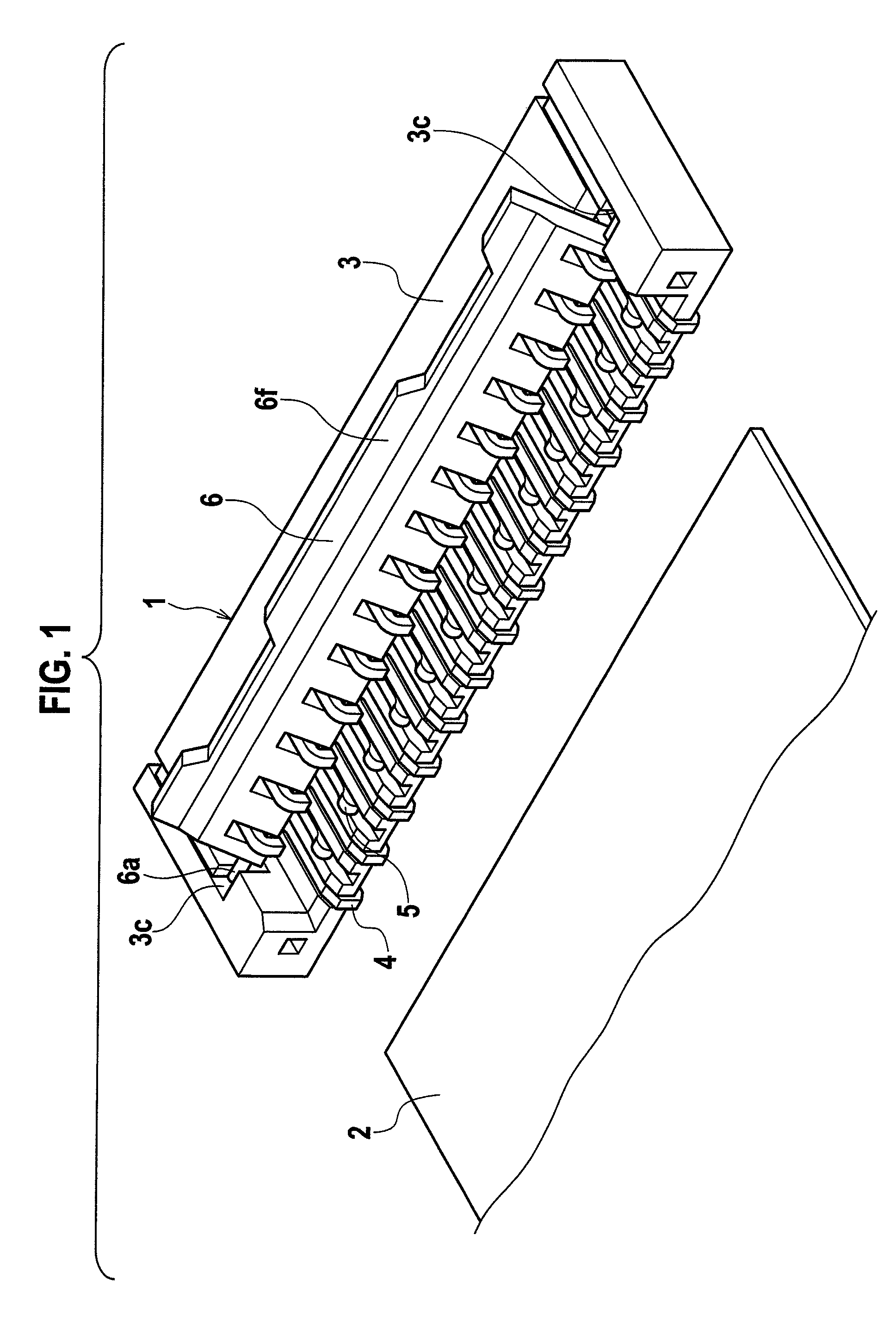
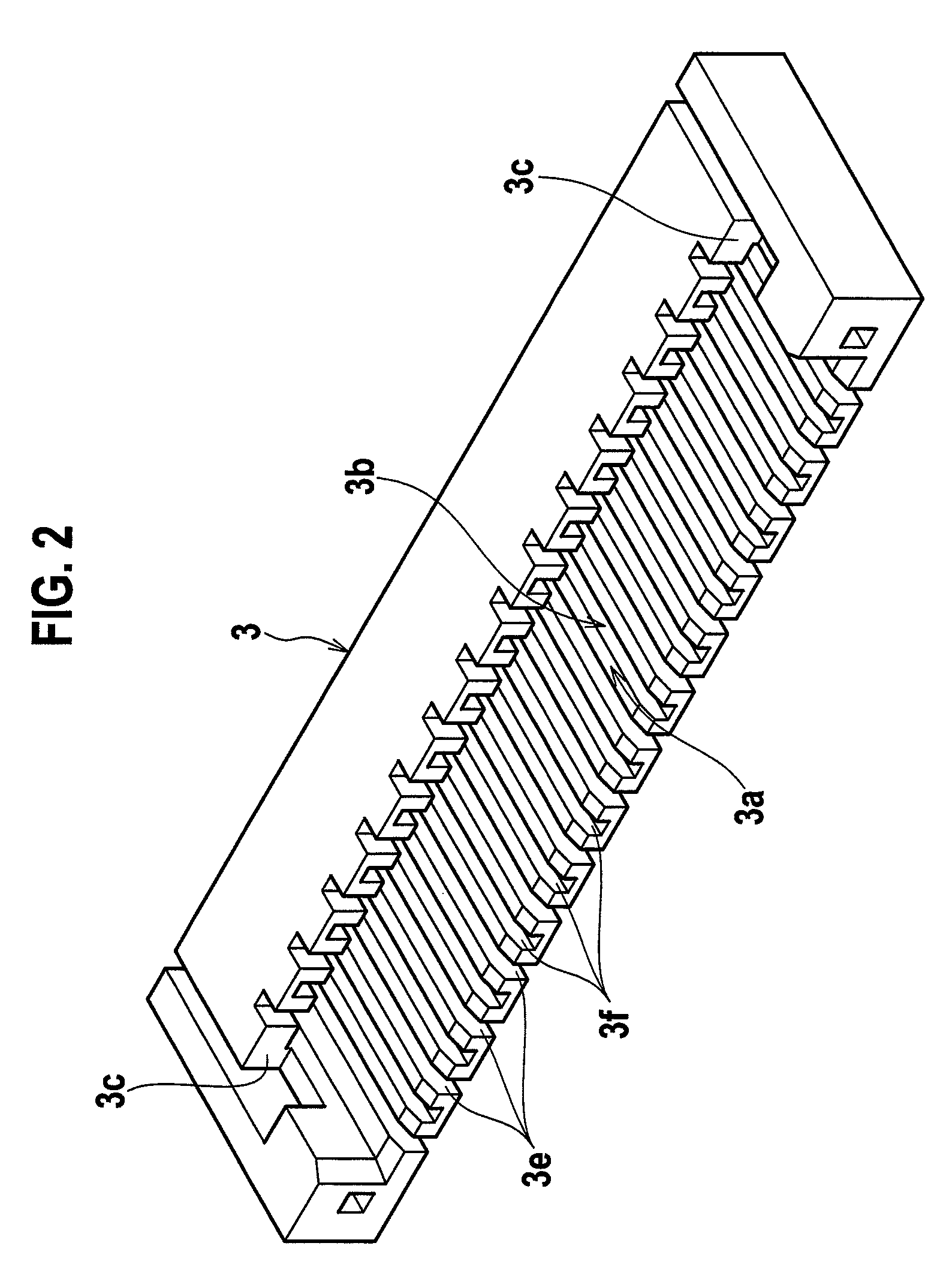
[0021]FIG. 1 is a perspective view of an external appearance of a cable connector according to a first embodiment of the present invention, FIG. 2 is a perspective view of an external appearance of a housing, FIG. 3 is a sectional view of a first contact and shows a state where a cover is opened, FIG. 4 is a sectional view of the first contact and shows a state where the cover is closed, FIG. 5 is a sectional view of a second contact and shows a state where the cover is opened, and FIG. 6 is a sectional view of the second contact and shows a state where the cover is closed.

[0022]A cable connector 1 includes an insulative housing 3 into which a sheet cable 2 such as FPC or FFC, having front surface and back surface. The cable connector 1 includes a plurality of insulative first contacts 4 which are arranged in one row at a predetermined pitch in the housing 3 and fixed and held therein. The first contact 4 includes a first contact unit 4a opposed to the front surface of the cable 2 a...

second embodiment

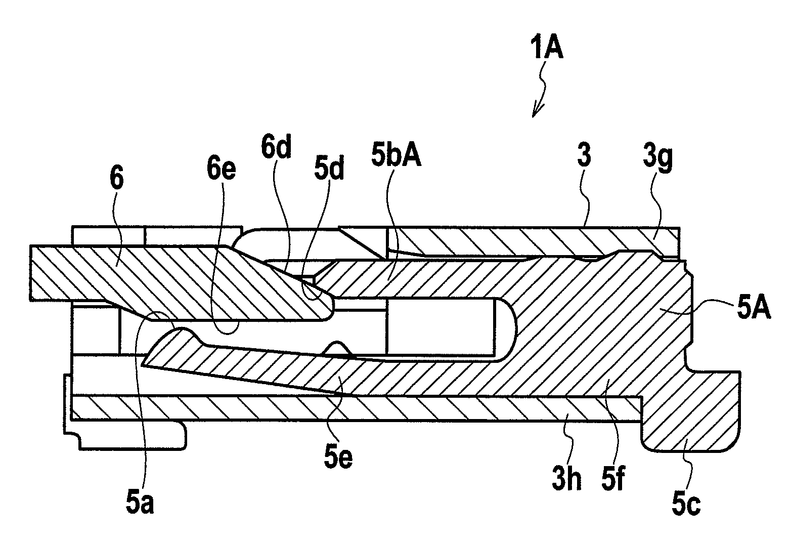
[0050]FIG. 7 is a sectional view of a first contact of a cable connector according to a second embodiment of the present invention, and shows a state where a cover is closed, and FIG. 8 shows a state where the cover is closed. The cable connector according to the second embodiment has like constituent elements as those of the cable connector according to the first embodiment. Thus, like constituent elements are designated with like reference symbols and redundant explanations thereof will be omitted.

[0051]In the cable connector 1A according to the second embodiment, an inclined portion 5d is provided on a tip end of a wall 5b A provided on an upper portion of a second contact 5A. The second embodiment is different from the first embodiment in that when the cover 6 is closed, the inclined portion 5d and the inclined surface 6d provided on the cover 6 abut against each other. That is, in the second embodiment, the inclined surface 6d of the cover 6 corresponds to an abutment unit. Whe...

third embodiment

[0055]FIG. 9 is a sectional view of a first contact of a cable connector according to a third embodiment of the present invention and shows a state where a cover is closed, and FIG. 10 shows a state where the cover is closed. The cable connector according to the third embodiment has like constituent elements as those of the cable connector of the first embodiment. Thus, like constituent elements are designated with like reference symbols and redundant explanations thereof will be omitted.

[0056]The third embodiment is different from the first and second embodiments in that in the cable connector 1B according to the third embodiment, an inclined surface 6dB of a cover 6B is provided with a projection 6g, an inclined portion 5d is provided on a tip end of the wall 5bB provided on an upper portion of the second contact 5B, the inclined portion 5dB and the inclined surface 6dB provided on the cover 6B abut against each other. That is, in the third embodiment, the projection 6g of the cov...


PUM


Abstract

A cable connector includes a housing, a first contact having a first contact unit opposed to a front surface of a cable and an engaging and pivoting unit opposed to a back surface of the cable, a second contact which is provided in the housing and which has a second contact unit opposed to the front surface of the cable and a wall opposed to the back surface of the cable, and a cover which is turnably supported on the engaging and pivoting unit by a through hole into which the engaging and pivoting unit is inserted and a cam unit engaged with the engaging and pivoting unit. The engaging and pivoting unit is engaged with the cam unit so that the cover can move in an inserting and releasing direction of the cable. The wall limits movement of the cover in an inserting direction of the cable.

Description

CROSS REFERENCE TO RELATED APPLICATIONS[0001]This application is based upon and claims the benefit of priority from prior Japanese Patent Application P2007-081567 filed on Mar. 27, 2007; the entire contents of which are incorporated by reference herein.BACKGROUND OF THE INVENTION[0002]The present invention relates to a cable connector, and more particularly, to a cable connector suitable for connecting a cable such as a flat ribbon cable and FPC.[0003]As a conventional cable connector, Japanese Patent Application Laid-open No. 2001-110483 (hereinafter, Patent Document 1) discloses a cable connector including a housing that receives an FPC cable, a plurality of first and second contacts fixed and held by the housing with a predetermined pitch, and an actuator that brings the FPC cable into contact with the first and second contacts under pressure.[0004]According to the Patent Document 1, the first and second contacts are respectively integrally provided with first and second contact ...

Claims


Application Information

Patent Timeline
Patent Type & Authority Patents(United States)
IPC IPC(8): H01R12/24H01R12/78H01R12/79
CPCH01R12/79H01R12/88H01R12/78
Inventor TANAKA, HIROHISAHASHIMOTO, SHUNSUKE
Owner MATSUSHITA ELECTRIC WORKS LTD
Why Eureka
Try Eureka