Adjustable ergonomic brace

a technology of ergonomic braces and adjustable brackets, which is applied in the direction of screws, nuts, bolts, etc., can solve the problems of inconvenient use, inconvenient adjustment, and inconvenient use, and achieve the effect of convenient us

Active Publication Date: 2009-05-19
KAUPTHING BANK
View PDF35 Cites 70 Cited by
  • Summary
  • Abstract
  • Description
  • Claims
  • Application Information

AI Technical Summary

Benefits of technology

[0005]Accordingly, objects of the invention include providing a knee brace which is compact, easy to use, which has many points of adjustment and is otherwise ergonomically configured. Preferably the adjustments should be simple and natural so that there is no need to resort to collateral written instructions.
[0006]Initially, relative to an illustrative preferred embodiment of the present knee brace, the knee brace stop construction operates at the periphery of the pivot arrangements so that the number of stop increments is maximized for the size of the pivot discs. Secondly, the stops may be operated by simple inward pressure on a push button associated with the flexion stop or the extension stop, to release the stop, followed by rotation of the stop to virtually any desired angle, and then followed by release of the push button to permit locking of the stop in the new angular position. With this simplified ergonomic construction, the stop adjustments may be easily made while the brace is mounted on the leg; and the mode of accomplishing stop adjustments is substantially self evident, with the shifting of the stops resulting in the natural or expected angular change in flexion or extension stops.
[0009]Additional features may include the provision of angular indicia on the outer surface of the outer one of said cover or closure plates and the implementation of the movable stop assembly by an outer, radially extending flat support member adjacent the indicia, preferably with a window through which the angular indicia may be seen. Further, the movable stop assembly may extend over the edge of one of said plates into the space between the two cover plates to cooperate with the locking steps. This construction contributes to the relatively thin overall configuration of the pivoting assembly, which may be only about one-half inch or about 1.3 cm thick. Also, to provide adequate strength and compactness, the brace and it components are preferably made of high strength material such as steel, titanium, zinc alloys, or other high strength metals or high strength plastic.
[0010]It is further noted that, in the preferred design, two catch plates are provided, and each of the stop assemblies includes a pin which seats in corresponding recesses in each of the two catch plates, to provide a balanced locking configuration for resisting forces applied between the struts to limit flexion or extension. The inner and outer cover plates may also have complementary recesses to more positively secure the stops at the selected angular position.

Problems solved by technology

Although many of the foregoing provided useful results, these prior art knee braces had shortcomings, in that they were unduly bulky, or were not simple to adjust, or did not have as many stop increments as would be desired, or were otherwise not ergonomically configured.

Method used


Image

  • Adjustable ergonomic brace
  • Adjustable ergonomic brace
  • Adjustable ergonomic brace

Examples


Embodiment Construction

[0029]While the specification describes particular embodiments of the present invention, those of ordinary skill can devise variations of the present invention without departing from the inventive concept.

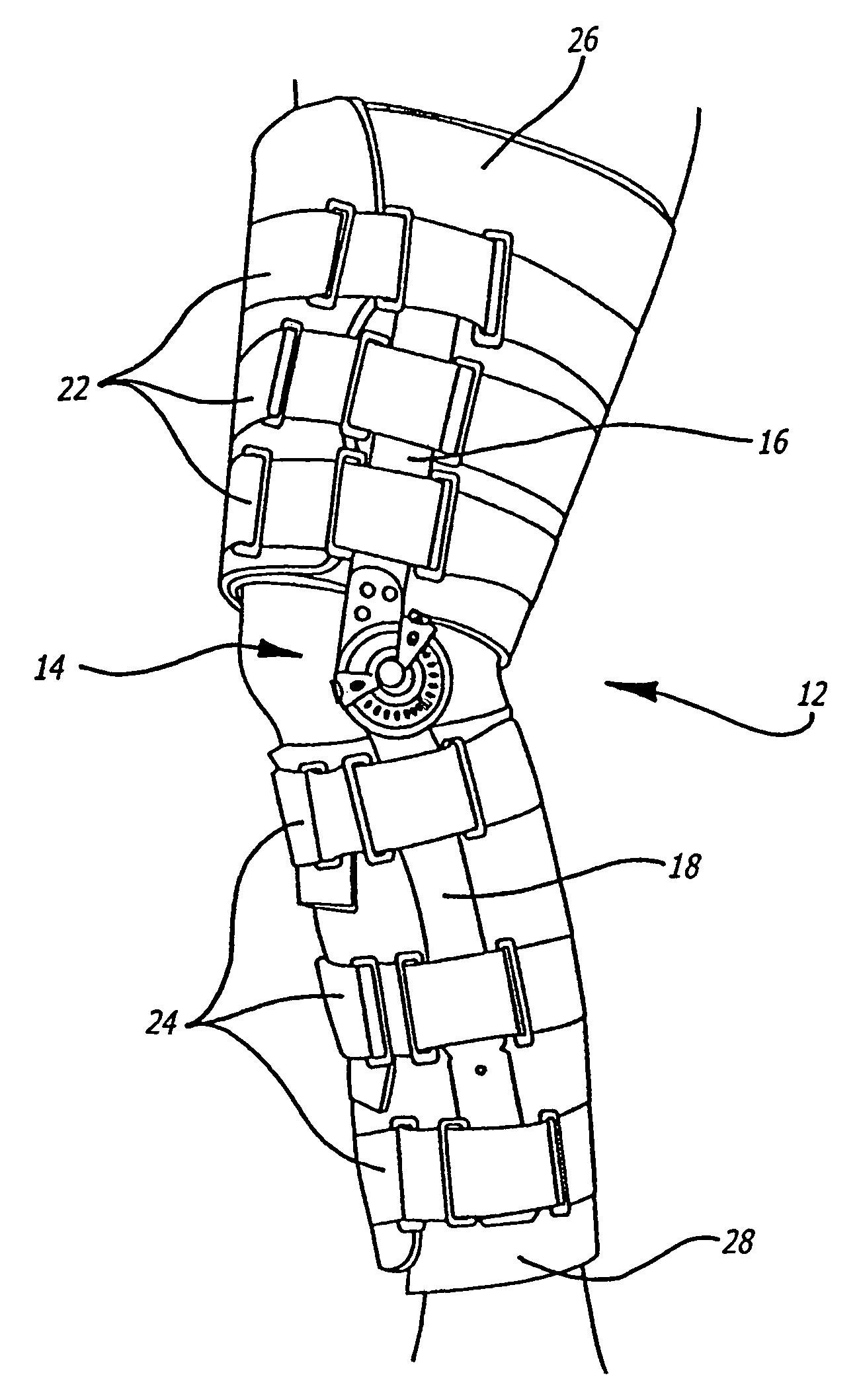
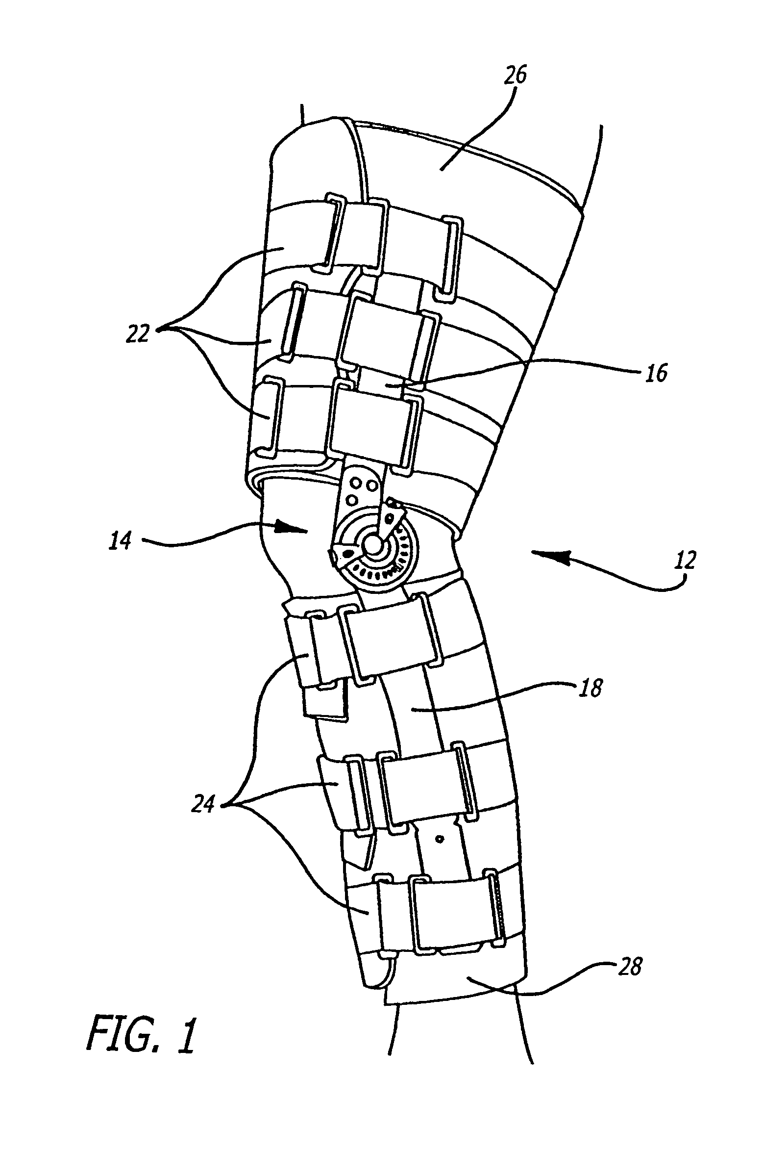
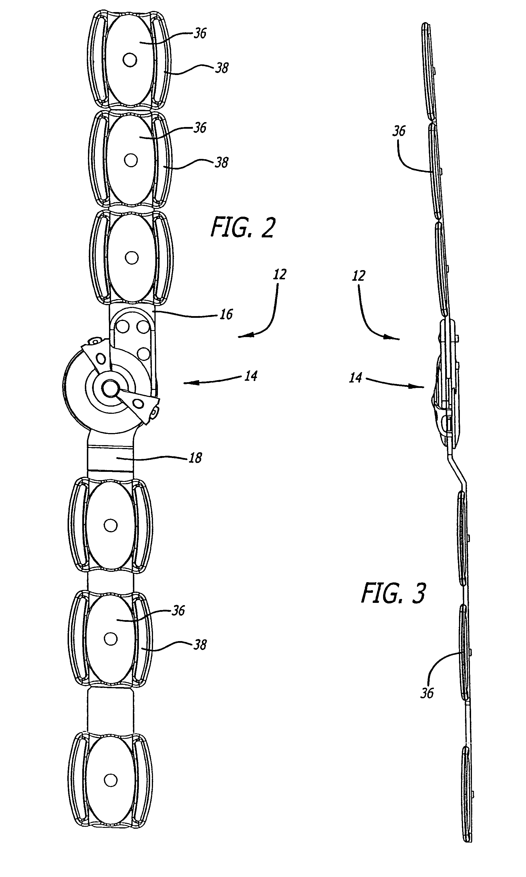
[0030]Referring more particularly to the drawings, FIG. 1 shows a leg brace 12 for the knee, including two struts extending up and down the leg from a central pivot assembly 14. Extending along the upper leg is a strut 16, and extending down the lower leg from the pivot assembly 14 is a lower strut 18. These struts are sometimes referenced as femoral struts (as extending along the femur or upper leg bone) and tibial struts (extending along the tibia, or the principal lower leg bone). A pivot assembly on the other side of the knee is also provided with struts extending up and down the leg, but these are not visible in FIG. 1.

[0031]To hold the struts in place on the leg are a series of straps 22 on the upper leg, and straps 24 on the lower leg. Suitable padding 26 is provided on the ...


PUM


Abstract

A knee brace is provided with push button actuatable stops, wherein the stops are biased outward into angular locking positions and inwardly directed pressure on the push buttons releases the stops and permits angular adjustment of the stops. A pair of catch plates with locking recesses facing inward, are provided, and outwardly biased locking pins engage the recesses in both catch plates. Each of the stop assemblies has an outwardly directed plate extending over the outer cover plate, and this plate is coupled to the physical stop member around the outer edge of the outer cover plate. The cover plate has angular indicia thereon, which may be viewed through windows in the outwardly extending plate portions of the stop assemblies.

Description

CROSS-REFERENCE TO RELATED APPLICATIONS[0001]This is a continuation-in-part of parent application having U.S. Ser. No. 10 / 675,324, filed Sep. 29, 2003, now U.S. Pat. No. 7,037,287, whose entire contents are hereby incorporated by reference.FIELD OF THE INVENTION[0002]This invention relates to ergonomic knee braces.BACKGROUND OF THE INVENTION[0003]In the field of adjustable knee braces or supports, it is desirable that the brace include arrangements for limiting the movement of the lower leg relative to the upper leg both as to bending the knee or flexion, and as to extension of the lower leg relative to the upper leg. Various knee brace arrangements have been proposed, and these have included upper struts for extending along the thigh, and lower struts for extending along the lower leg or calf. These are normally provided both on the inside or medial side of the leg and also on the outer or lateral side of the leg; and the medial and lateral struts are normally padded, and provided ...

Claims


Application Information

Patent Timeline
Patent Type & Authority Patents(United States)
IPC IPC(8): A61F5/00A44B21/00F16B39/04F16D3/00F16B39/00F16B35/00A45B9/00A61H3/02E04H15/46A44B99/00A61F5/01
CPCA61F5/0125A61F2005/0167Y10T16/5385Y10T16/54Y10T403/32377Y10T24/44573Y10T403/32327Y10T403/32606Y10T24/44744Y10T403/32262Y10T24/4634
Inventor CORMIER, DAVIDGRIM, TRACY E.IGLESIAS, JOSEPH M.COBAR, HUGO A.BATMAN, JANELLE R.HU, IRVINGLEE, WENDEEJONES, JACQUELINE
Owner KAUPTHING BANK
Why Eureka
Try Eureka