

High speed arbitrary waveform generator
a generator and high-speed technology, applied in the field of arbitrary waveform generators, can solve the problem that each d/a converter is inherently limited in bandwidth, and achieve the effect of overcomplicating bandwidth limitations and limited bandwidth
- Summary
- Abstract
- Description
- Claims
- Application Information
AI Technical Summary
Benefits of technology
Problems solved by technology
Method used
Image

Examples
Embodiment Construction
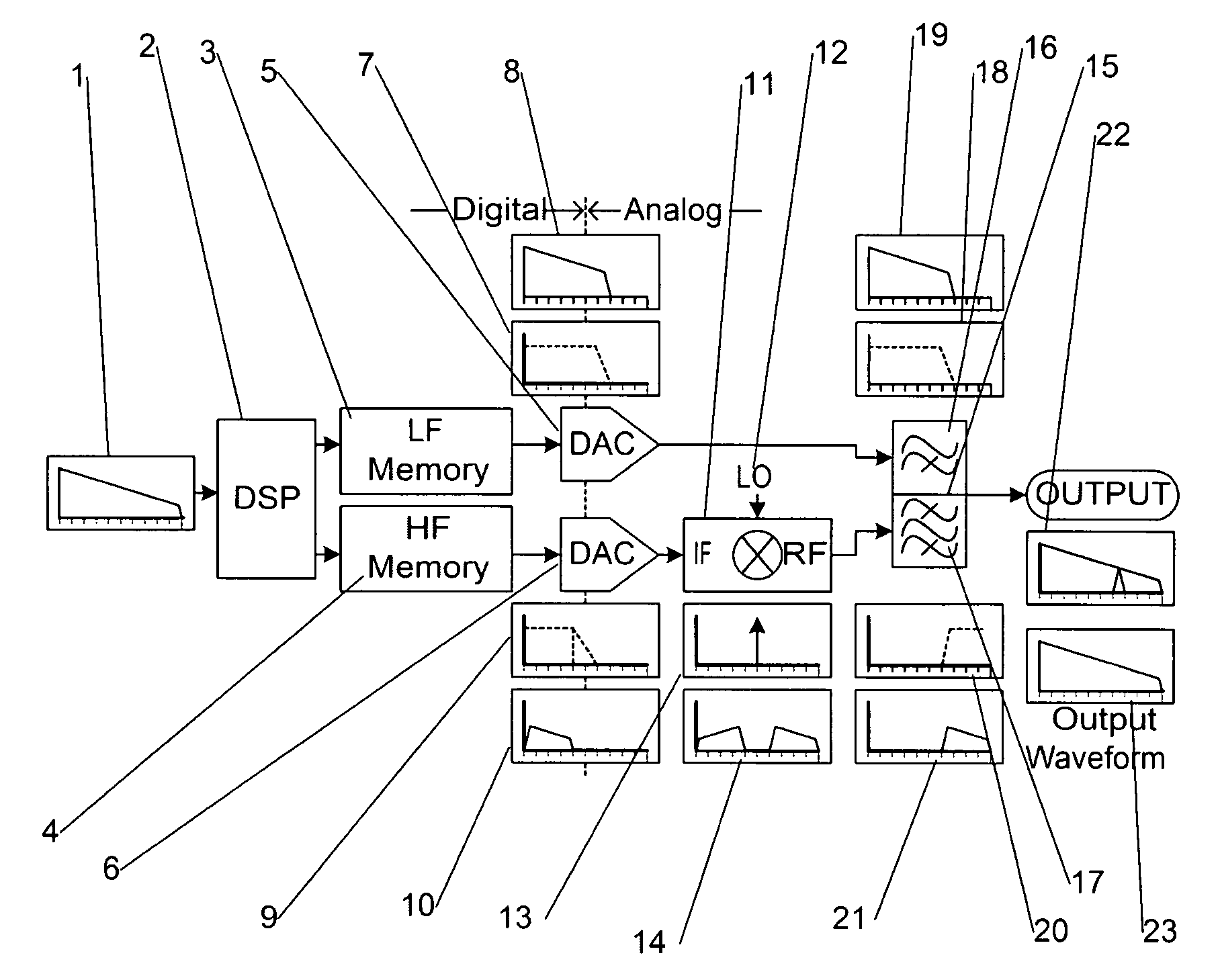
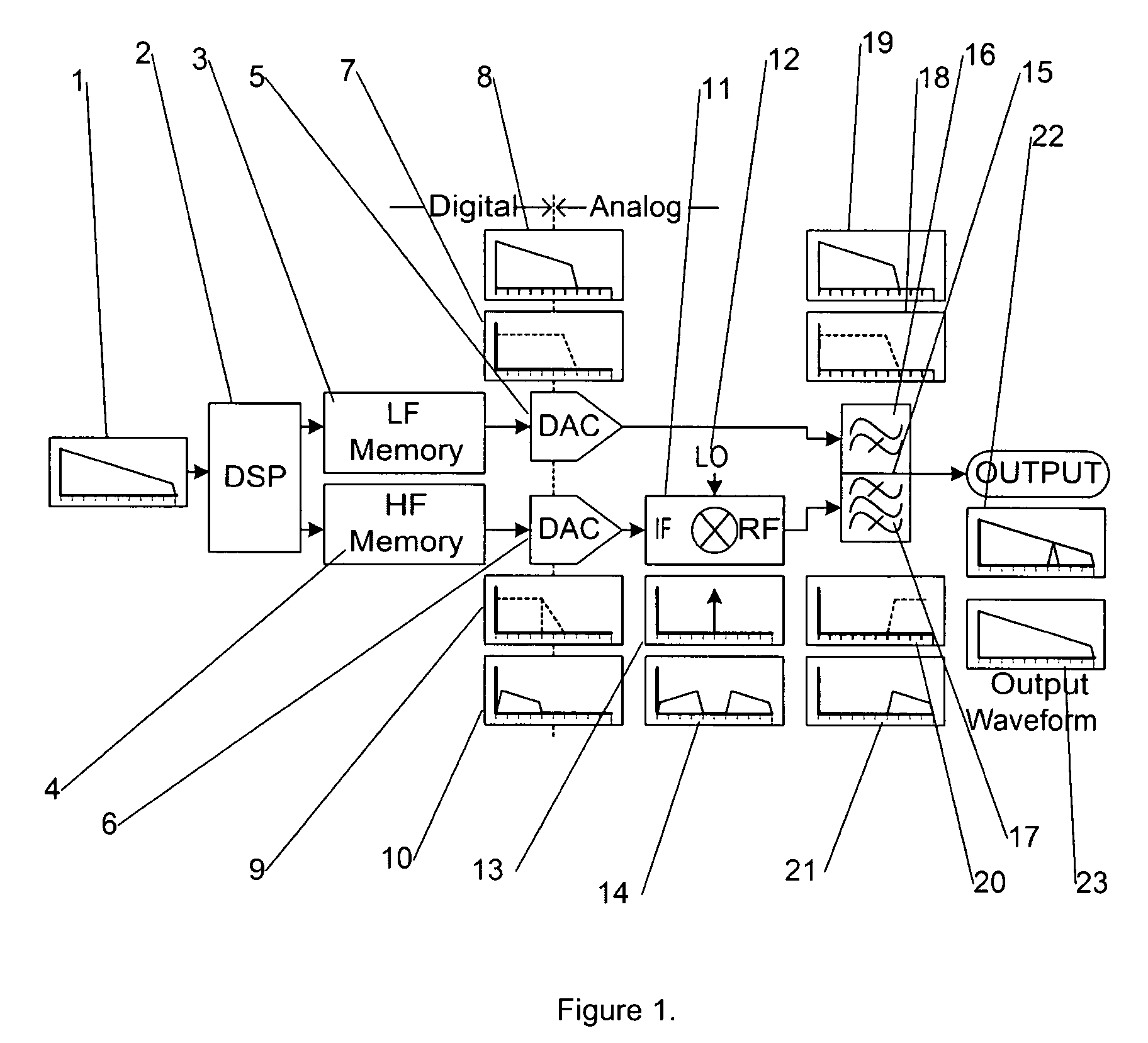
[0015]FIG. 1 shows an arbitrary waveform generator constructed in accordance with to the present invention. The generation of high-speed signals starts with designation of a desired waveform [1] where it is understood that the desired waveform [1] is in digital form or has a possible digital representation. It is also understood that the desired waveform [1] is shown as spectral content (i.e. in the frequency-domain) as opposed to an equivalent time-domain representation as will all waveforms described. This is only because the present method is best understood by examination from a frequency-domain perspective. The invention may also be applied to a time-domain defined signal.
[0016]It should be pointed out that traditionally, this digital waveform would have been presented to a D / A converter such as D / A converter [5] either directly or through a high-speed memory element such as [3]. But the response of the D / A converter [7] shows that it has insufficient bandwidth to generate the ...
PUM
 Abstract
Description
Claims
Application Information