Data driver and light emitting diode display device including the same

a technology of light-emitting diodes and data drivers, applied in the direction of instruments, static indicating devices, etc., can solve the problem of no method of measuring and controlling the real current in each pixel

Active Publication Date: 2006-06-29
SAMSUNG DISPLAY CO LTD
View PDF11 Cites 67 Cited by
  • Summary
  • Abstract
  • Description
  • Claims
  • Application Information

AI Technical Summary

Benefits of technology

[0016] A third aspect of the present invention is achieved by providing a data driver including a voltage digital-analog converter to generate a data voltage corresponding to the data, a current digital-analog converter to generate a sensing current corresponding to the data, and a comparator that receives a pixel current that flows in a pixel corresponding to the data voltage and is fed back from the pixel, and compares the pixel current with the sensing current to generate a first control signal, having a high voltage level, and a second control signal, having a low voltage level, the first and second control signals differing in their widths corresponding to the difference between the pixel current and the sensing current, and a current adjuster to be turned on and off by the first and second control signals to allow a current to flow in a first capacitor in response to the first control signal and the stored current to flow out from the first capacitor in response to the second control signal, and control the data voltage to be supplied to the pixel on the basis of increase or decrease of the voltage stored or being charged in the first capacitor.
[0017] A fourth aspect of the present invention is achieved by providing a method of driving a light emitting diode display device, including generating a data voltage and a sensing current corresponding to data, supplying the data voltage to a pixel, and receiving a pixel current that flows in a pixel corresponding to the data voltage and is fed back from the pixel, increasing or decreasing the amount of current charging a first capacitor, and controlling a level of the data voltage to be supplied to the pixel on the basis of a level of voltage applied to the first capacitor varied corresponding to the increase or the decrease of the amount of current charging the first capacitor.
[0018] A fifth aspect of the present invention is achieved by providing a method of driving a light emitting diode display device, including generating a data voltage and a sensing current corresponding to data, supplying the data voltage to a data line for a first period of one horizontal period, comparing the sensing current with the pixel current in a pixel corresponding to the data voltage for a second period of one horizontal period, and increasing or decreasing the amount of current charging a first capacitor on the basis of comparison, and controlling the level of the data voltage to be supplied to the pixel on the basis of the level of voltage applied to the first capacitor that is varied corresponding to the increase or decrease of the amount of current charging the first capacitor.
[0019] Another aspect of the invention provides a method for controlling image brightness corresponding to data received in an organic light emitting display device having a pixel for emitting light. The method includes generating a data voltage and a sensing current corresponding to the data, storing the data voltage in a capacitor, supplying the data voltage stored in the capacitor to the pixel to generate a pixel current corresponding to the data voltage, comparing the pixel current with the sensing current corresponding to the data, and controlling the data voltage to provide a desired image brightness by incrementing the data voltage if the pixel current is lower than the sensing current and decrementing the data voltage if the pixel current is higher than the sensing current.

Problems solved by technology

Further, in the conventional light emitting diode display device 100, there is no method of measuring and controlling the real current in each pixel 40.

Method used


Image

  • Data driver and light emitting diode display device including the same
  • Data driver and light emitting diode display device including the same
  • Data driver and light emitting diode display device including the same

Examples


Embodiment Construction

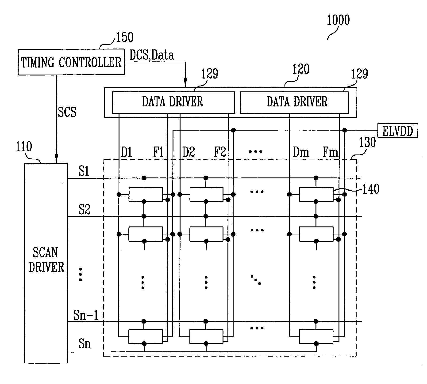
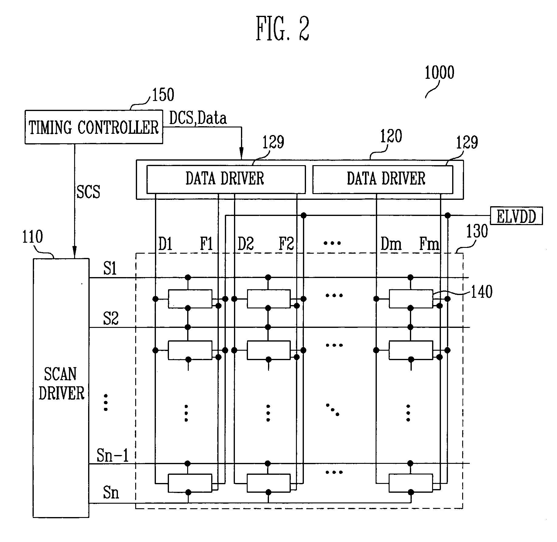
[0030]FIG. 2 illustrates a light emitting diode display device 1000 according to an embodiment of the present invention. The light emitting diode display device 1000 of the invention includes a display region 130 that has pixels 140 formed on a region that is defined by intersection of scan lines S1 through Sn, data lines D1 through Dm, and lines having a feedback function or feedback lines F1 through Fm, a scan driver 110 to drive scan lines S1 through Sn, a data driving part 120 to drive data lines D1 through Dm, and a timing controller to control the data driving part 120.

[0031] The display region 130 includes the pixels 140 coupled with the scan lines S1 through Sn, the data lines D1 through Dm, and the feedback lines F1 through Fm. The scan lines S1 through Sn may be formed along a row direction and each supply a scan signal to the pixels 140. The data lines D1 through Dm may be formed along a column direction and each supply a data signal to the pixels 140. The feedback lines...


PUM


Abstract

A data driver and a light emitting diode display device including the circuit that cause a pixel current through the light emitting diode to be independent of the threshold voltage of a transistor driving the light emitting diode. The data driver includes a voltage digital-analog converter for generating a data voltage and a current digital-analog converter for generating a sensing current, both corresponding to input data, and a voltage control block for receiving the pixel current that corresponds to the data voltage and is fed back from the pixel to the voltage control block changing the amount of current charging a capacitor in the voltage control block and controlling the data voltage supplied to the pixel. Controlling and adjusting the data voltage helps uniformity in the display brightness regardless of non-uniformity of transistors in each pixel.

Description

CROSS-REFERENCE TO RELATED APPLICATIONS [0001] This application claims priority to and the benefit of Korean Patent Applications No. 10-2004-0112538 and No. 2004-112539, both filed on Dec. 24, 2004, in the Korean Intellectual Property Office, the entire content of both of which is incorporated herein by reference.BACKGROUND [0002] 1. Field of the Invention [0003] The present invention relates to a data driver and a light emitting diode display device including the same, and more particularly, to a data driver and a light emitting diode display device that display an image with desired brightness. [0004] 2. Discussion of Related Art [0005] Various flat panel displays have recently been developed as alternatives to the relatively heavy and bulky cathode ray tube (CRT) display device. The flat panel displays include liquid crystal display devices (LCD), field emission display devices (FED), plasma display panels (PDP), light emitting diode display devices (OLED), and the like. [0006] A...

Claims


Application Information

Patent Timeline
Patent Type & Authority Applications(United States)
IPC IPC(8): G09G3/30
CPCG09G3/3283G09G2300/0842G09G2300/0861G09G2320/0295G09G2320/029G09G2320/043G09G2310/027
Inventor CHOI, SANG MOOKIM, HONG KWONKWON, OH KYONG
Owner SAMSUNG DISPLAY CO LTD
Why Eureka
Try Eureka