Eureka AIR delivers breakthrough ideas for toughest innovation challenges, trusted by R&D personnel around the world.

Gradient insensitive split-core digital to analog converter

a digital to analog converter, gradient-sensitive technology, applied in the direction of digital-analog converters, physical parameters compensation/prevention, instruments, etc., can solve the problems of not being able to fabricate accurate resistors across the resistor value range, not being able to meet the requirements of a large range of resistor values, etc., to achieve a substantial insensitivity or reduce the sensitivity of gradient- gradient gradient gradient gradient gradient gradien

Inactive Publication Date: 2005-08-30
ANALOG DEVICES INT UNLTD
View PDF10 Cites 72 Cited by
  • Summary
  • Abstract
  • Description
  • Claims
  • Application Information

AI Technical Summary

Benefits of technology

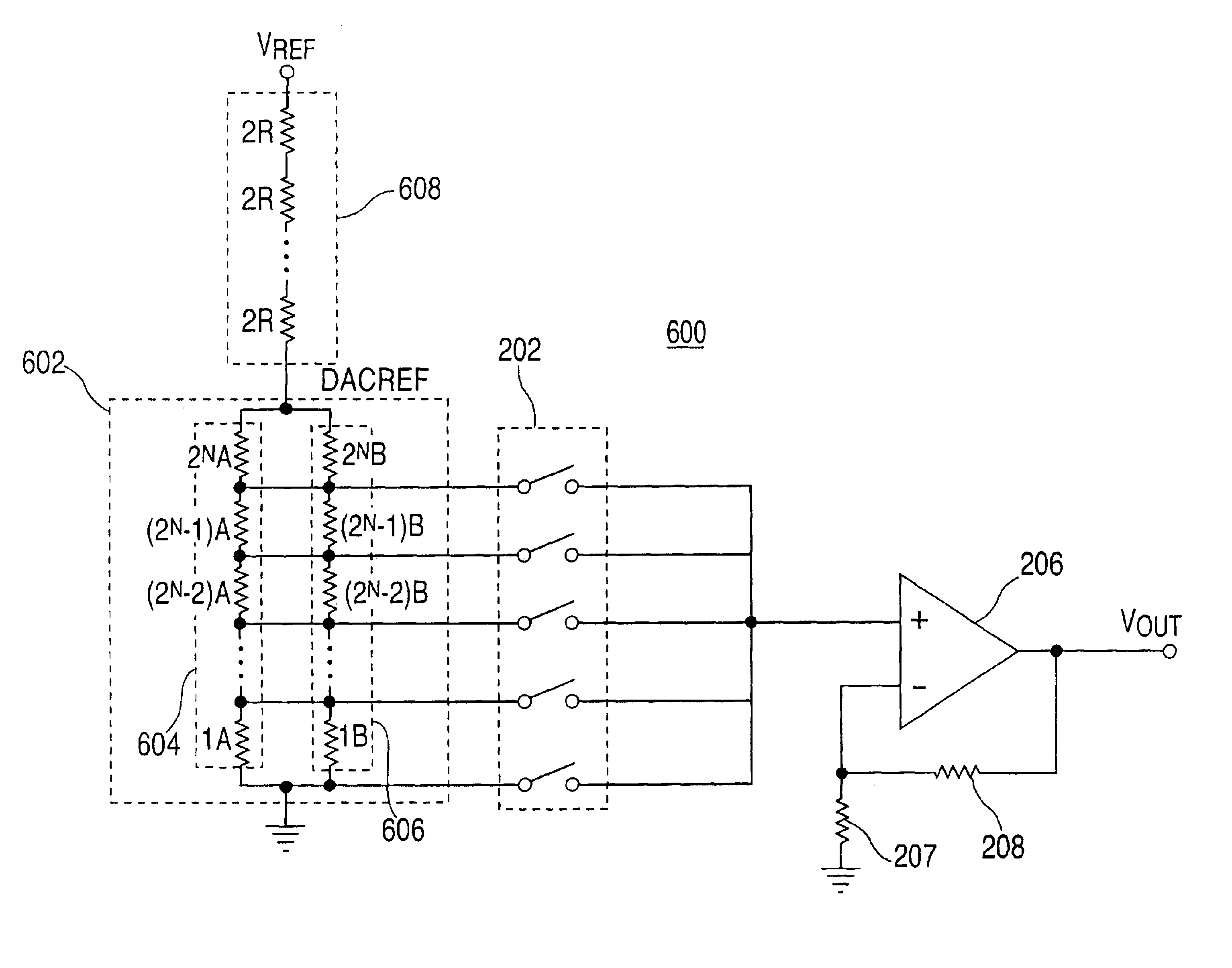
[0016]In accordance with this and other objects of the present invention, DAC circuitry and methods which provide digital to analog conversion with reduced sensitivity or substantial insensitivity to error gradients are provided. Split-core resistive elements are described that may be used in DAC circuitry to offset the effects of error gradients on the linearity of the available analog output voltages corresponding to various digital input signals. For example, the split-core resistive elements in accordance with the principles of the present invention include at least two resistor strings that may be configured such that a common centroid exists with respect to the error gradients. Accordingly, a plurality of resistor string output voltages may be combined in order to at least partially cancel the effects of the error gradients.

Problems solved by technology

This type of DAC is logically simple to implement, however, it is typically not the most practical type of converter to use because the range of resistor values often becomes very large.
In particular, accurate resistors across the range of resistor values become difficult to fabricate as the resolution of the binary-weighted resistor DAC increases (i.e., as N increases).
Therefore, unlike with the binary-weighted resistor DAC, the problem of often requiring a large range of resistor values is not present.
The R-2R ladder DAC, however, does not guarantee monotonicity, which may be particularly important in applications such as control systems.
Similarly, a decrease in the digital input signal does not guarantee a decrease in the analog output voltage of the R-2R ladder DAC.
A significant drawback associated with using resistor string DACs, however, is that the linearity of the analog output voltages corresponding to different digital input signals is limited by the precision with which the voltage division is accomplished.
As the resolution of the resistor string DAC increases, the number of resistors increases exponentially, increasing the likelihood that the resistors being used will have reduced precision.
Accurate resistor matching can also be a problem in another type of DAC, the interpolating amplifier DAC, which operates using the principle of a segmented DAC and is explained in greater detail below.
Due to various technological limitations, the matching of the resistor string resistors for larger resolution DACs becomes extremely difficult.
One factor that limits the resistor matching, and therefore the accuracy of voltage division by the resistor string, is the introduction of error gradients (e.g., linear error gradients).
Accordingly, variations in the sheet resistance and geometry of the resistive materials cause imperfections during the fabrication of resistors.
Moreover, variations in contact resistance may also contribute to the introduction of linear error gradients.
For example, resistors used in resistor string DACs or interpolating amplifier DACs may be subject to thermal linear error gradients.
In this case, variations in the temperature conditions surrounding the various resistors of a resistor string may result in the resistors being subject to undesirable deviations in resistor values.

Method used


Image

  • Gradient insensitive split-core digital to analog converter
  • Gradient insensitive split-core digital to analog converter
  • Gradient insensitive split-core digital to analog converter

Examples


Embodiment Construction

[0031]This invention relates to DACs that are substantially insensitive or have at least reduced sensitivity to the effects of error gradients. More particularly, various embodiments of resistor string DACs and interpolating amplifier DACs having at least partial insensitivity to error gradients are described below in accordance with the principles of the present invention.

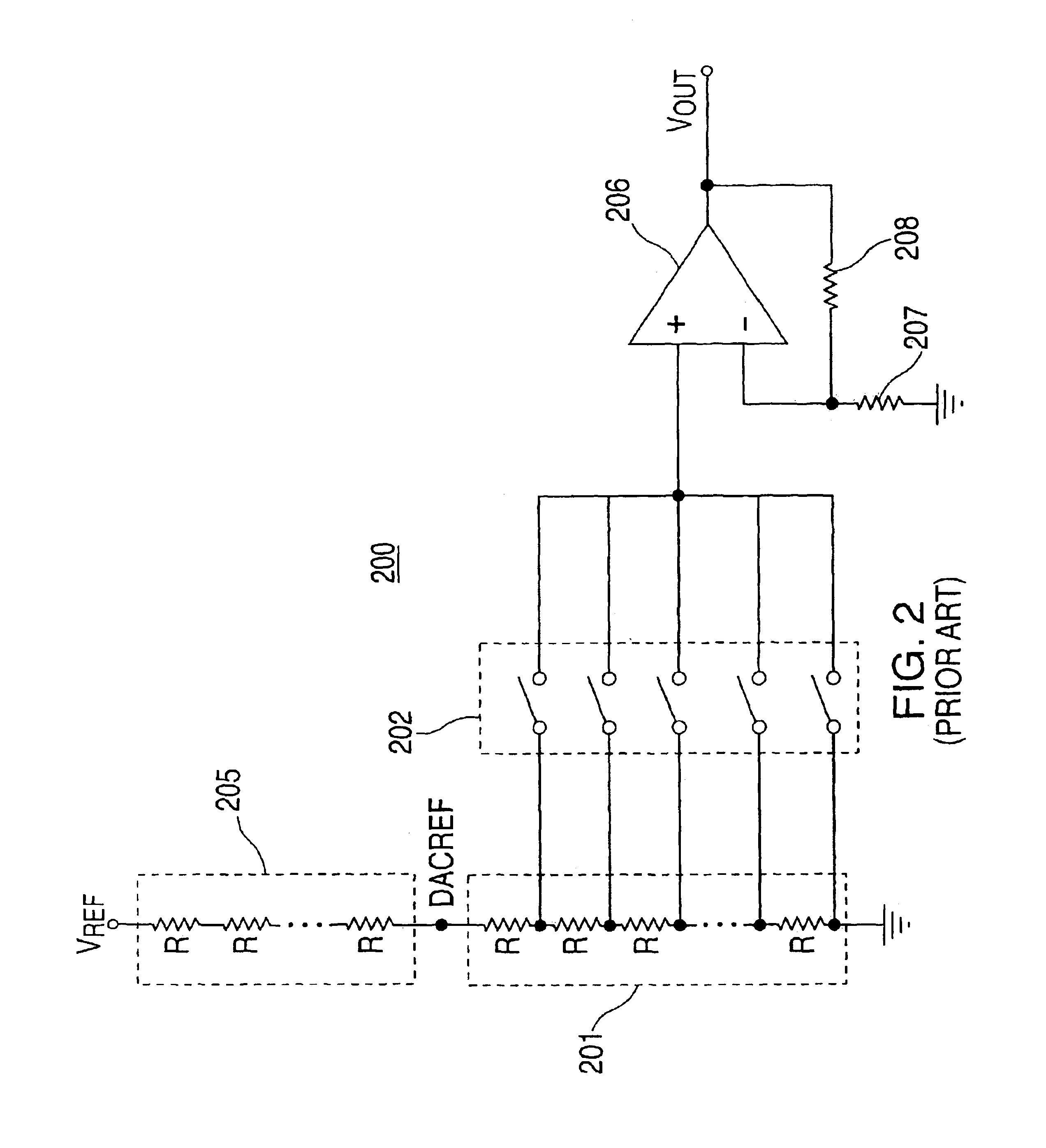
[0032]To better understand the detrimental effects that error gradients have on the performance of a DAC, and how the present invention compensates for such effects, conventional resistor string and interpolating amplifier DACs will first be explained.

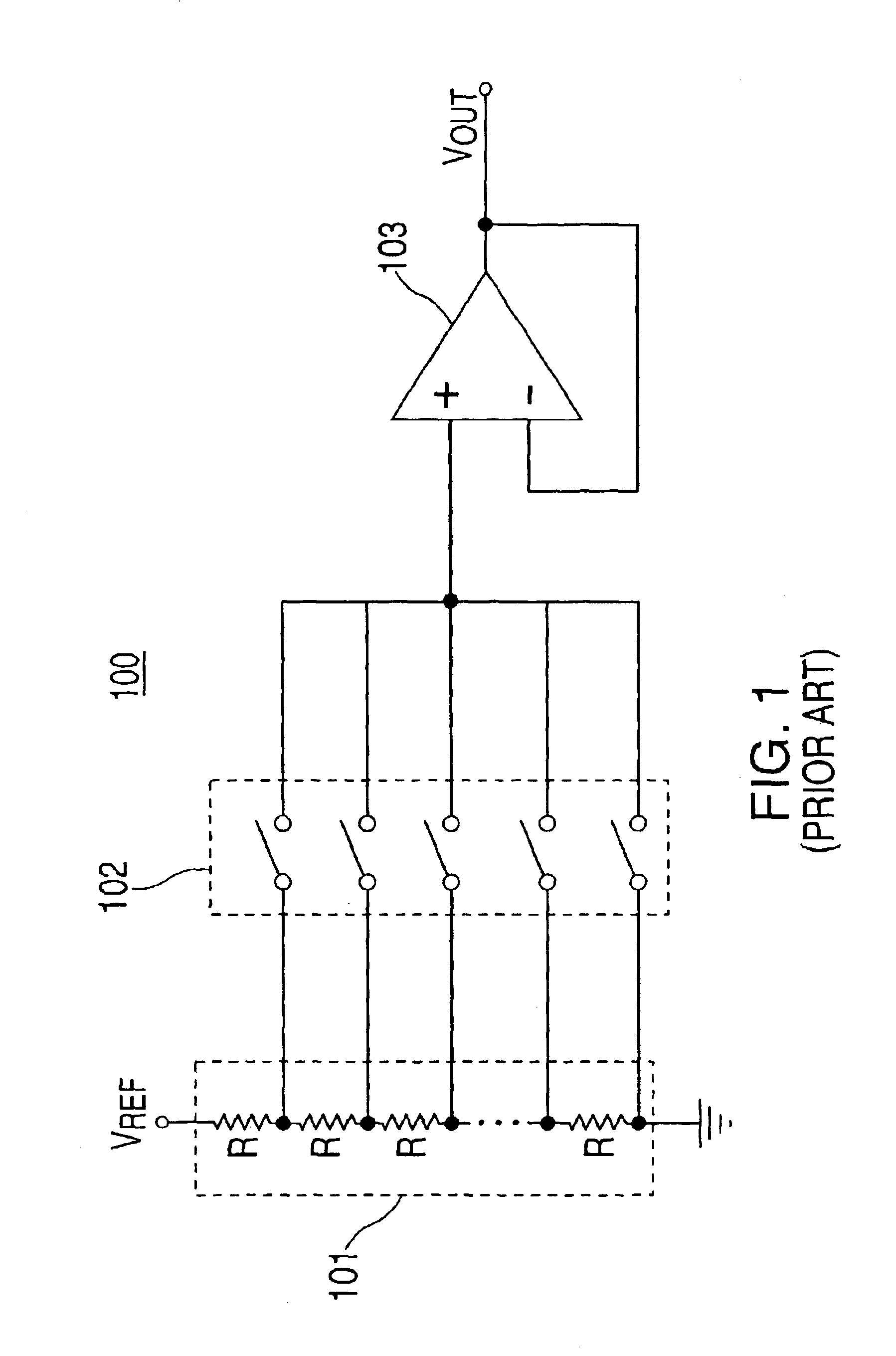
[0033]A conventional resistor string DAC 100 that may be subject to the effects of linear error gradients is shown in FIG. 1. DAC 100 includes resistor string 101, which includes 2N ideally identical resistors (e.g., each resistor of resistor string 101 has a resistance as close to R as possible). The nodes between successive series connected resistors are coupled, t...


PUM


Abstract

Digital to analog converter circuits and methods are provided for producing an analog output voltage indicative of a digital input signal with at least partial insensitivity to error gradients. Described are split-core resistive elements, which include a plurality of one-dimensional or multi-dimensional resistive strings, that may be used to reduce or substantially eliminate the effects that error gradients have on the linearity of the analog output voltages of a resistive string or interpolating amplifier DACs. The resistor strings that make up the split-core resistive elements are configured in such a manner that combining respective output voltages from each of the resistor strings results in an analog output voltage that is at least partially insensitive to the effects of error gradients.

Description

BACKGROUND OF THE INVENTION[0001]The present invention relates to digital to analog converters (DACs). More particularly, this invention relates to circuits and methods for providing a split-core DAC that is at least partially insensitive to the effects of error gradients.[0002]The general purpose of a DAC is to transform digital input signals into analog output voltages. In other words, a DAC takes the binary bits of a digital input signal, which originate from a computer or other type of discrete circuitry, and converts the digital input signal into an analog output voltage that can be used to drive analog devices (e.g., motor controllers or audio circuitry).[0003]There are several types of DACs that are well known and are capable of converting digital input signals into analog output voltages. An example of a commonly used DAC is the binary-weighted resistor DAC, which uses N binary-weighted resistors (where N is the number of bits of a digital signal to be converted). This type ...

Claims


Application Information

Patent Timeline
IPC IPC(8): H03M1/78H03M1/74H03M1/06H03M1/76
CPCH03M1/0678H03M1/0643H03M1/765
Inventor REMPFER, WILLIAM C.MALIK, HASSANBRUBAKER, JAMES L.
Owner ANALOG DEVICES INT UNLTD
Why Eureka
Eureka Blog
Learn More