Method and system for reheating flue gas using waste heat to maintain dry chimney stack operation

a technology of waste heat and dry chimney stack, applied in indirect heat exchangers, lighting and heating apparatus, emission prevention, etc., can solve the problems of corrosive flue gas, high capital expenditure and time consumption of these types of chimney stacks, and achieve the effect of optimizing energy efficiency in industrial plant operations

Active Publication Date: 2016-06-16
RAINBOW ENERGY CENT LLC
View PDF10 Cites 4 Cited by
  • Summary
  • Abstract
  • Description
  • Claims
  • Application Information

AI Technical Summary

Benefits of technology

[0012]The Flue Gas Reheat System of the present invention is a unique and useful method and system of continuously and proactively controlling flue gas chimney stack temperature at a prudent temperature

Problems solved by technology

If the temperature of the flue gas drops below the flue gas dew point, condensation of water vapor and acid gases ensues, which are very corrosive for these types of chimney stacks.
In the past, other reheat systems have been generally avoided in the industry due to high cost of operation and more significant maintenance requirements.
One solution to address this problem is to add a corrosive resistant heat exchanger in direct contact with the saturated flue gas to keep the flue gas warm, which is costly.
Another option is to redesign and replace the chimney stack so it operates in a wet condition, below the flue gas dew point, but this option is both capitally intensive and time consuming, limiting the magnitude and cost effect

Method used


Image

  • Method and system for reheating flue gas using waste heat to maintain dry chimney stack operation
  • Method and system for reheating flue gas using waste heat to maintain dry chimney stack operation
  • Method and system for reheating flue gas using waste heat to maintain dry chimney stack operation

Examples


Embodiment Construction

[0032]It is to be understood, however, that even though numerous characteristics and advantages of the present invention have been set forth in the foregoing description, together with details of the structure and function of the invention, the disclosure is illustrative only, and changes may be made in detail, especially in matters of shape, size, and arrangement of parts within the principles of the invention to the full extent indicated by the broad general meaning of the terms in which the appended claims are expressed.

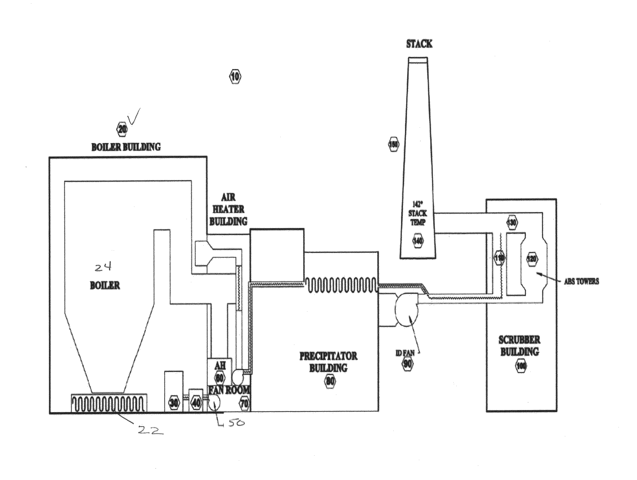
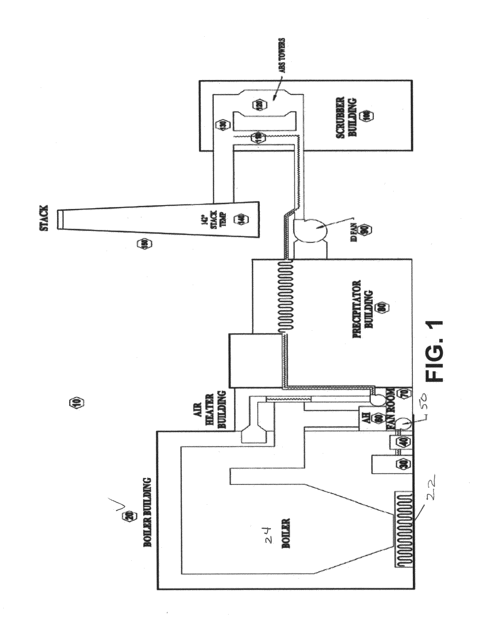
[0033]To understand the flue gas reheat system and method of the present invention, it is necessary to first understand the components of a typical energy or industrial plant and the flow of flue gas through the plant.

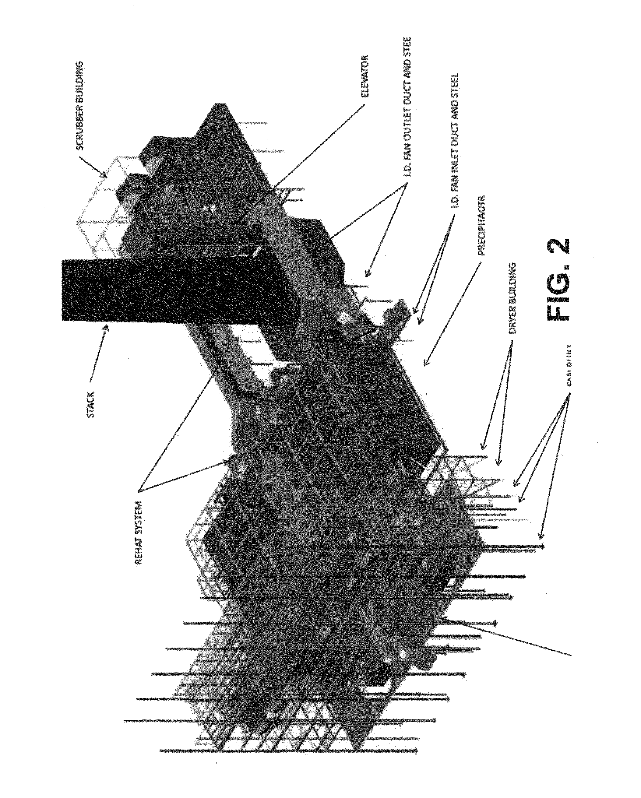
[0034]Referring to FIG. 1, a schematic of a typical energy plant 10, and FIG. 2, a schematic of the interior of the plant as shown in FIG. 1, the plant includes the following major components: a boiler building 20, a pulverizer 30, a primary air damp...


PUM


Abstract

Flue gas is a by-product of many energy and industrial plants and is typically emitted through a chimney stack. If the flue gas temperature in the chimney stack drops below the flue gas dew point, condensation of water vapor and acid gases ensues. These gases are very corrosive for chimney stacks designed to operate in a dry condition. The Flue Gas Reheat System of the present invention continuously and proactively manages flue gas chimney stack temperatures above the dew point in order to optimize emission control and effectuate energy efficiency improvements in industrial plants. Waste heat is harvested from the exterior surfaces of existing steam and pollution control equipment through conduction, convection and radiation. This heat is transferred to a working fluid. The working fluid is then directly mixed with the flue gas prior to the flue gas entering the chimney stack to raise the temperature of (or re-heat) the flue gas above its dew point to maintain a dry chimney stack condition. The use of residual or waste heat from throughout the plant and the minimal equipment required to harvest the waste heat reduces the operating cost and improves the overall reliability of the system. This method is useful in many industries, including electric power generation plants and other energy intensive process industries that seek emission control and various boiler and fuel energy efficiency improvements, many of which improvements result in a reduction in normal chimney stack temperature.

Description

CROSS REFERENCE TO RELATED APPLICATION[0001]This application claims priority to U.S. Provisional Application 62 / 124,367 filed on Dec. 16, 2014, which is hereby incorporated by reference in its entirety.FIELD OF INVENTION[0002]The present invention relates to the fields of industrial plants, waste heat and thermal amplification. Specifically, the present invention relates to the utilization of both high grade (above 150° F.) and low grade (below approximately 150° F.) residual or waste heat available throughout a typical industrial process plant to re-heat flue gas before it exits a plant chimney stack to maintain dry chimney stack operations.BACKGROUND OF THE INVENTION[0003]Energy and industrial plants are required by law to capture certain contaminants emitted from plant operations. Some of these contaminants are generated by combustion in furnaces and / or boilers utilized to generate steam for various purposes. Flue gas, a natural by-product of combustion, carries a number of these...

Claims


Application Information

Patent Timeline
IPC IPC(8): F23J15/08F28C3/02
CPCF28C3/02F23J15/08F23J2215/20F23J2217/50F28D21/001Y02P20/10Y02P80/10
Inventor POZARNSKY, JARED D.
Owner RAINBOW ENERGY CENT LLC
Why Eureka
Try Eureka