Disk drive with airflow control and fins at a transitional surface between base surfaces

a technology of airflow control and disk drive, which is applied in the direction of electrical apparatus construction details, instruments, record information storage, etc., can solve the problem that parts of the base bottom surface cannot be made closer to the magnetic disk, and achieve the effect of suppressing reducing the current of the motor, and reducing the turbulence of airflow

Inactive Publication Date: 2009-05-19
WESTERN DIGITAL TECH INC
View PDF13 Cites 9 Cited by
  • Summary
  • Abstract
  • Description
  • Claims
  • Application Information

AI Technical Summary

Benefits of technology

[0008]One approach to reduce the flutter of the magnetic disk is to make a gap between the bottom surface of the base and the magnetic disk small to suppress a flow of gas between the magnetic disk and the base bottom surface. However, as the base bottom surface is made closer to the magnetic disk to increase air resistance is increased, thereby increasing the current of the spindle motor.
[0009]The present invention has been accomplished on the basis of the circumstances as described above, and a feature of the invention is to suppress the flutter of a magnetic disk to reduce the amount of motor current.

Problems solved by technology

For example, since it is necessary to ensure the turning space of an actuator, part of the base bottom surface cannot be made closer to the magnetic disk.

Method used


Image

  • Disk drive with airflow control and fins at a transitional surface between base surfaces
  • Disk drive with airflow control and fins at a transitional surface between base surfaces
  • Disk drive with airflow control and fins at a transitional surface between base surfaces

Examples


Embodiment Construction

[0029]The specific embodiments to which the present invention is applied will be hereinafter described. For clarification of explanation, the following description and drawings are suitably omitted and simplified. Further, in the drawings, the same elements are indicated by the same reference numerals, and to clarify explanation, duplicate explanation or the reference numerals of the drawings are omitted.

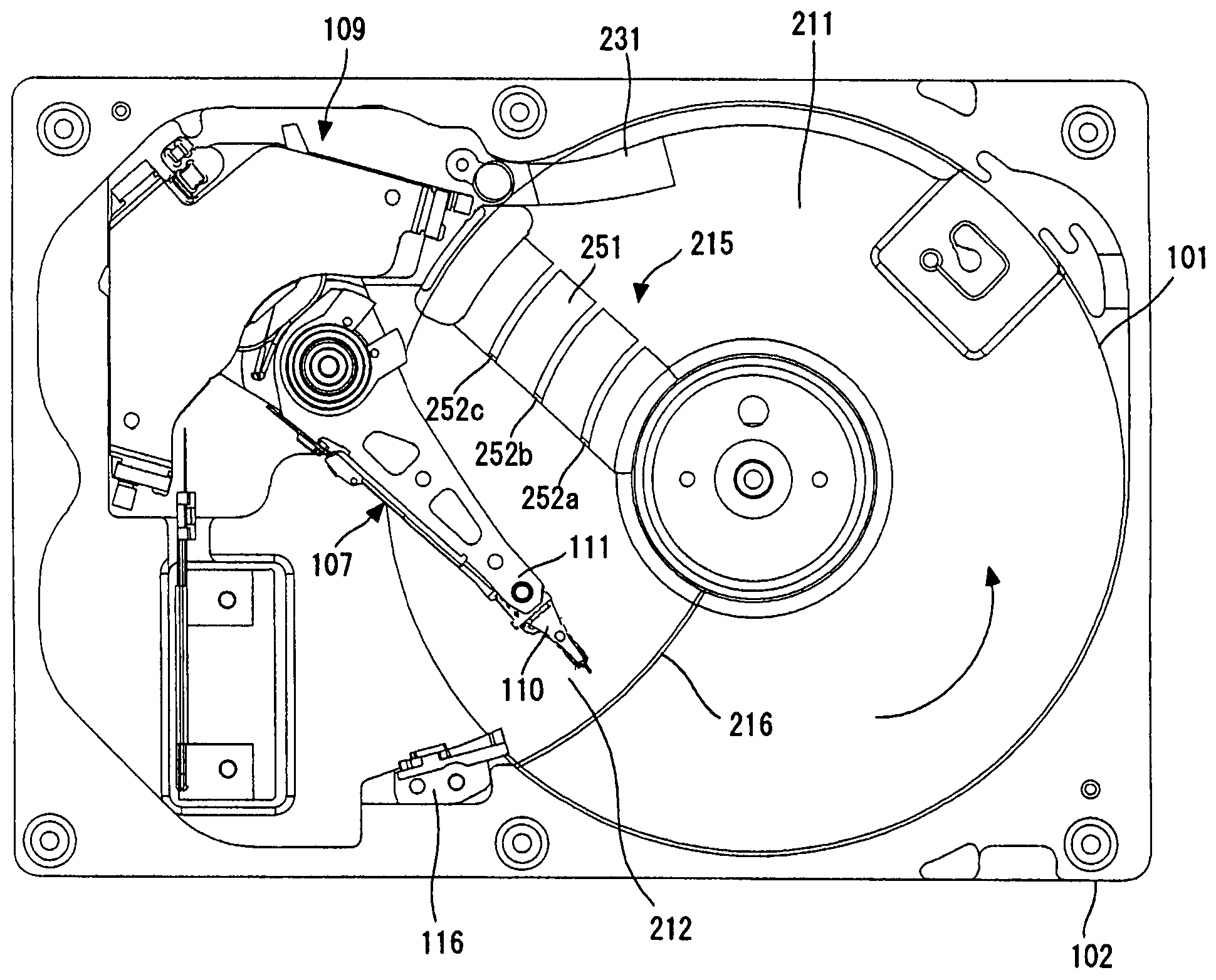
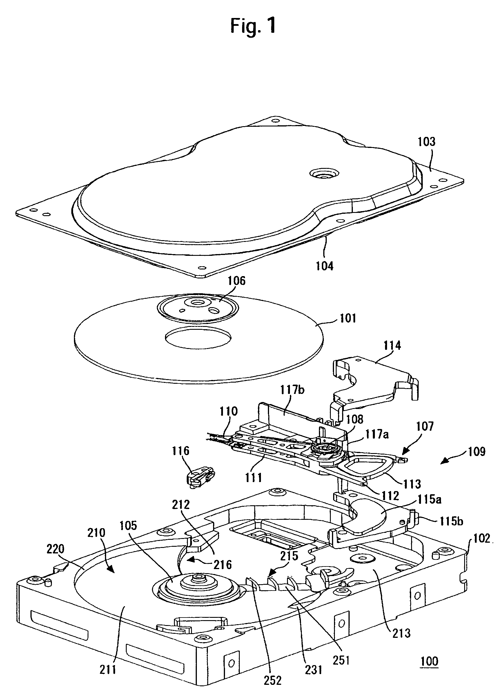
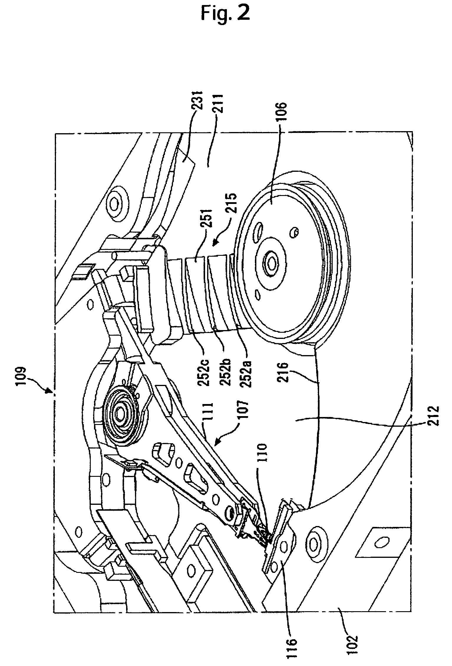
[0030]Specific embodiments to which the present invention is applied will be described in detail with reference to the drawings. The disk drive in the present embodiment is characterized by the structure of the base thereof. For better understanding of the present invention, first, the whole structure of a hard disk drive (hereinafter referred to as HDD) as one example of the disk drive will be described. FIG. 1 is an exploded perspective view schematically showing the structure of a HDD 100 according to the present embodiment. In FIG. 1, numeral 101 denotes a recording medium for s...


PUM

PropertyMeasurementUnit
inclined angleaaaaaaaaaa

Abstract

Embodiments of the invention suppress the occurrence of turbulence in a disk drive. In one embodiment, an HDD includes a spindle motor for rotating a magnetic disk, and a base for housing the spindle motor therein. The base includes a first bottom surface opposed to the magnetic disk, and a second bottom surface that is opposed to the magnetic disk and that is larger in distance to the magnetic disk than the first surface. A step is formed between the first bottom surface and the second bottom surface, where rotation of the magnetic disk produces an airflow running from the first surface toward the second surface. The step is provided with upright fins extending from the first surface toward the second surface which are stood upright.

Description

CROSS-REFERENCES TO RELATED APPLICATIONS[0001]This application claims priority from Japanese Patent Application No. JP2004-373078, filed Dec. 24, 2004, the entire disclosure of which is incorporated herein by reference.BACKGROUND OF THE INVENTION[0002]The present invention relates to a disk drive, and more particularly, to control of an airflow generated by rotation of a recording disk in a disk drive.[0003]Data storage devices using various types of media such as optical disks and magnetic tapes are known in the art. Among them, hard disk drives (hereinafter referred to as HDDs) have become popular as storage devices for computers to such an extent that they are one type of the storage devices indispensable for today's computers. Further, not limited to computer systems, HDDs are expanding more and more in application because of their excellent characteristics. For example, HDDs are used for moving picture recording / reproducing devices, car navigation systems, cellular phones, and ...

Claims


Application Information

Patent Timeline
Patent Type & Authority Patents(United States)
IPC IPC(8): G11B33/08
CPCG11B5/6005G11B25/043G11B33/08G11B5/40
Inventor SUZUKI, TAKAOCHAWANYA, TAKESHITAKEUCHI, KOHICHI
Owner WESTERN DIGITAL TECH INC
Why Eureka
Try Eureka