
Systems for distributing data over a computer network and methods for arranging nodes for distribution of data over a computer network

a technology of computer network and data distribution, applied in the field of systems for distributing data over a computer network, can solve the problem that the bandwidth of the computer system at another location is only sufficient, and achieve the effect of short time duration

Inactive Publication Date: 2009-05-19
NYIAX INC
View PDF6 Cites 23 Cited by
  • Summary
  • Abstract
  • Description
  • Claims
  • Application Information

AI Technical Summary

Benefits of technology

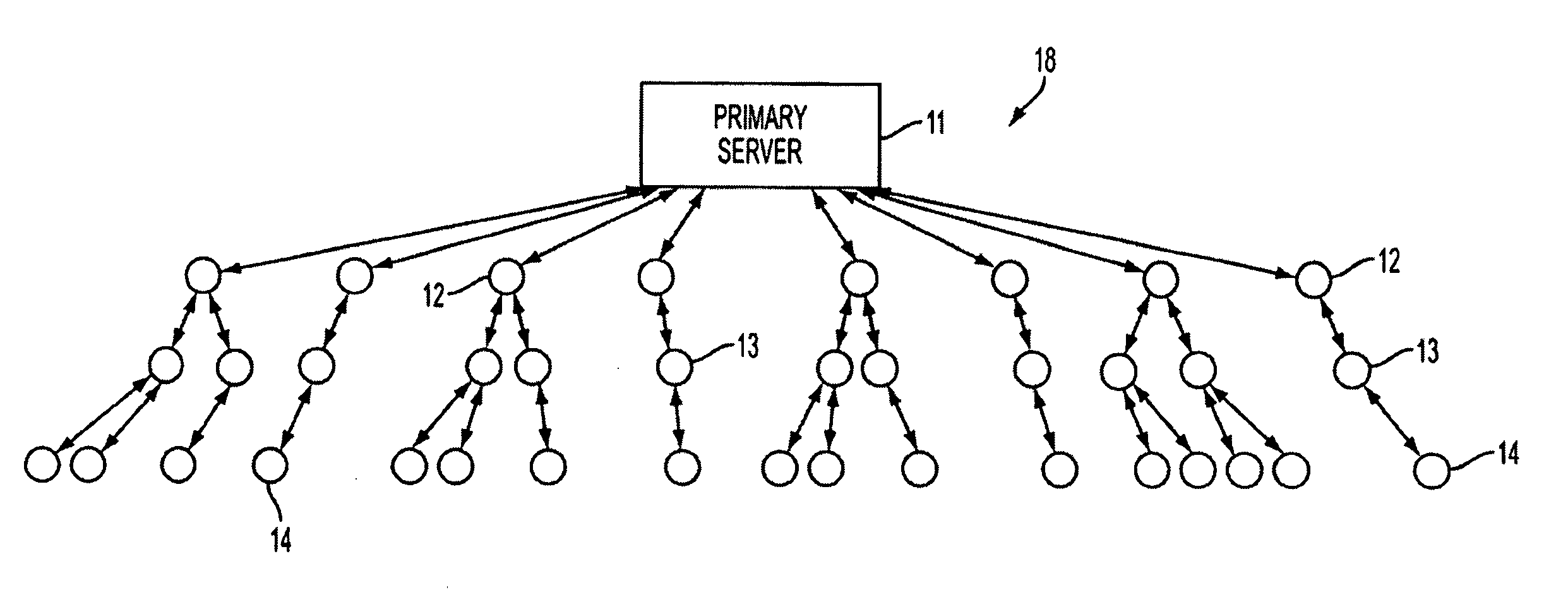
[0018]Various embodiments of the present invention relate to a system for distributing data (e.g., content data) over a computer network and a method of arranging receiver nodes in a computer network such that the capacity of a server is effectively increased (e.g., the capacity of a server may be effectively multiplied many times over; the capacity of the server may be effectively increased exponentially). In one embodiment the present invention may take advantage of the excess capacity many receiver nodes possess, and may use such receiver nodes as repeaters. The distribution system may include node(s) having database(s) which indicate ancestor(s) and / or descendant(s) of the node so that reconfiguration of the distribution network may be accomplished without burdening the system's primary server. An embodiment of the present invention may include a process for configuring a computer information distribution network having a primary server node and user nodes docked (i.e., connected) in a cascaded relationship, and reconfiguring the network in the event that a user node departs from the network. In one example (which example is intended to be illustrative and not restrictive), the process may include the steps of providing a new user node (or connection requesting user node) with a connection address list of nodes within the network, having the new user node (or connection requesting user node) go to (or attempt to go to) the node at the top of the connection address list, determine whether that node is still part of the distribution network, and connect thereto if it is, and if it is not, to go to (or attempt to go to) the next node on the connection address list. In another example (which example is intended to be illustrative and not restrictive), when a user node departs from the distribution network, a propagation signal may be transmitted to the nodes below it in the network, causing them to move up in the network in a predetermined order. In another example (which example is intended to be illustrative and not restrictive), the present invention may provide a decentralized approach which provides, to each new user node (or connection requesting user node) a path back to the root server.

Problems solved by technology

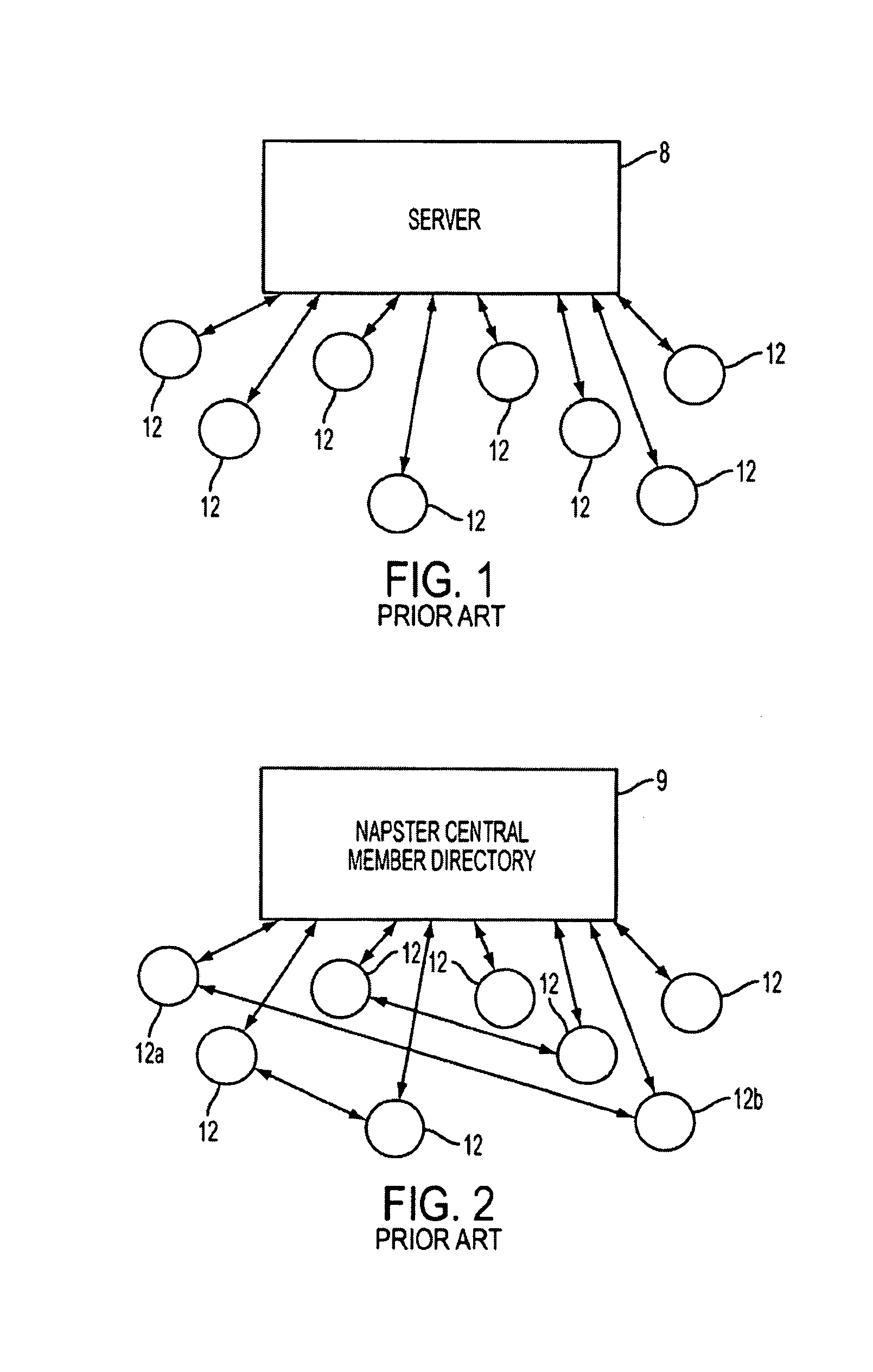
A computer system at another location may have only sufficient bandwidth to effectively exchange data with only one other computer system.

Method used


Image

  • Systems for distributing data over a computer network and methods for arranging nodes for distribution of data over a computer network
  • Systems for distributing data over a computer network and methods for arranging nodes for distribution of data over a computer network
  • Systems for distributing data over a computer network and methods for arranging nodes for distribution of data over a computer network

Examples


Embodiment Construction

[0059]Detailed embodiments of the present invention are disclosed herein; however, it is to be understood that the disclosed embodiments are merely illustrative of the invention that may be embodied in various forms. In addition, each of the examples given in connection with the various embodiments of the invention are intended to be illustrative, and not restrictive. Further, the figures are not necessarily to scale, some features may be exaggerated to show details of particular components. Therefore, specific structural and functional details disclosed herein are not to be interpreted as limiting, but merely as a representative basis for teaching one skilled in the art to variously employ the present invention.

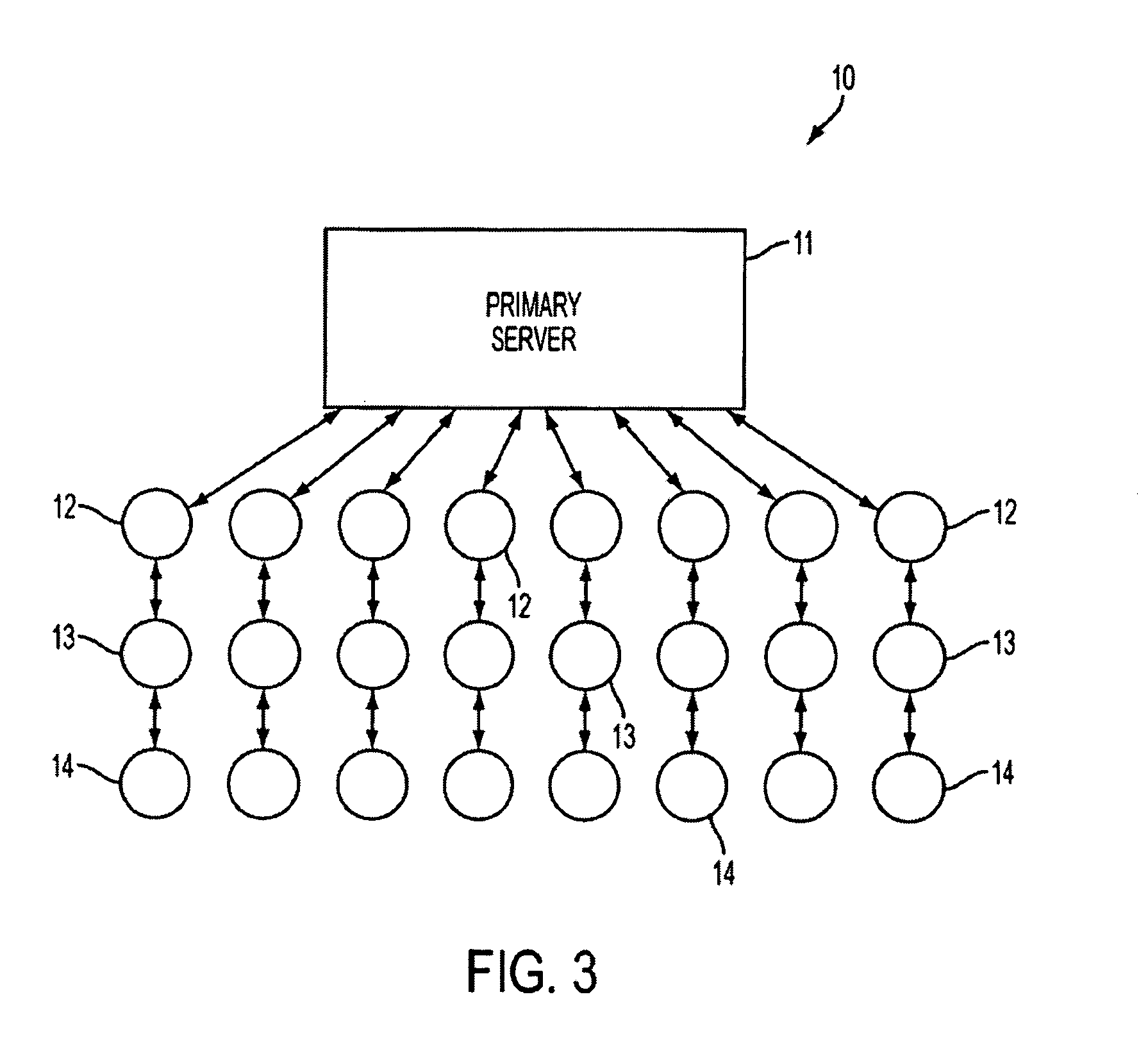
[0060]Referring now to FIG. 3, an illustration of a linear propagation arrangement 10 of a computer network according to an embodiment of the present invention is shown. In this embodiment, the primary server node (or simply, server) 11 provides content data (e.g., streaming...


PUM


Abstract

A system and method for propagating a network topology model of a binary tree topology network through the network. The network includes a plurality of nodes, including a root node and at least one leaf node, operatively networked together. Each leaf node provides a propagate network topology model message to the parent node docked uptree of and with the providing leaf node. Each of the plurality of nodes that receives the propagate network topology model message forms a network topology model representing one or more paths from the receiving node to nodes downtree of the receiving node, stores the model in a memory accessible to the receiving node, and provides a propagate network topology model message containing the network topology model to the parent node docked uptree of and with the receiving node. A network topology model is thereby propagated through the network.

Description

[0001]This patent application is a continuation-in-part of commonly assigned patent application “System for Distributing Content Data Over a Computer Network and Method of Arranging Nodes for Distribution of Data Over a Computer Network”, Ser. No. 09 / 952,907, Filed Sep. 13, 2001, now U.S. Pat. No. 7,035,933, and claims the benefit of the filing date of commonly assigned provisional patent application “Systems for Distributing Data Over A Computer Network And Methods For Arranging Nodes For Distribution Of Data Over A Computer Network”, Ser. No. 60 / 586,952, filed Jul. 9, 2004.FIELD OF THE INVENTION[0002]Various embodiments of the present invention relate to systems for distributing data (e.g., content data) over a computer network and methods of arranging nodes for distribution of data (e.g., content data) over a computer network. In one example (which example is intended to be illustrative and not restrictive), the systems and methods of the present invention may be applied to the d...

Claims


Application Information

Patent Timeline
Patent Type & Authority Patents(United States)
IPC IPC(8): G06F15/16G06F15/173H04L29/08
CPCH04L12/1854H04L41/12H04L67/16H04L67/104H04L67/06H04L67/1095H04L67/1097H04L67/1091H04L67/1048H04L67/1046H04L67/1089H04L65/4076H04L65/611H04L67/51
Inventor O'NEAL, MIKETALTON, JOHN P.
Owner NYIAX INC
Learn More