Acute angle metal stock bender

a technology of metal stock and bending rod, which is applied in the direction of metal-working apparatus, manufacturing tools, forging/hammering/pressing machines, etc., can solve the problems of difficult to achieve the acute angle bend, large amount of shop space, and complex apparatus, so as to eliminate the use of electricity and reduce the hydraulic pressure

Active Publication Date: 2009-05-26
BULLE MARSHALL R
View PDF5 Cites 9 Cited by
  • Summary
  • Abstract
  • Description
  • Claims
  • Application Information

AI Technical Summary

Benefits of technology

[0011]A pneumatic source is used to power a hydraulic pump to provide pressurized hydraulic fluid to the cylinder. The pump has an integral hydraulic fluid reservoir for hydraulic fluid and a foot control. The foot control turns on the pump and controls the pump speed and can also retract the ram by allowing the hydraulic fluid to return to the reservoir and reduce the hydraulic pressure. This arrangement completely eliminates the use of electricity to power or to control operate the apparatus. Since a shop environment is rugged and hazardous, this complete elimination of electricity ensures that an operator will not be injured by electricity when using this equipment.

Problems solved by technology

An acute angle bend presents a problem compared to smaller bends because the force required is large and must be exerted over a long distance.
This is difficult to achieve with a cylinder and ram because the long distance requires a long cylinder and ram which are both prone to buckling under such a large force.
This apparatus is fairly complex and requires a substantial amount of shop space because of the size of the frame and the size of the arc.

Method used


Image

  • Acute angle metal stock bender
  • Acute angle metal stock bender
  • Acute angle metal stock bender

Examples


Embodiment Construction

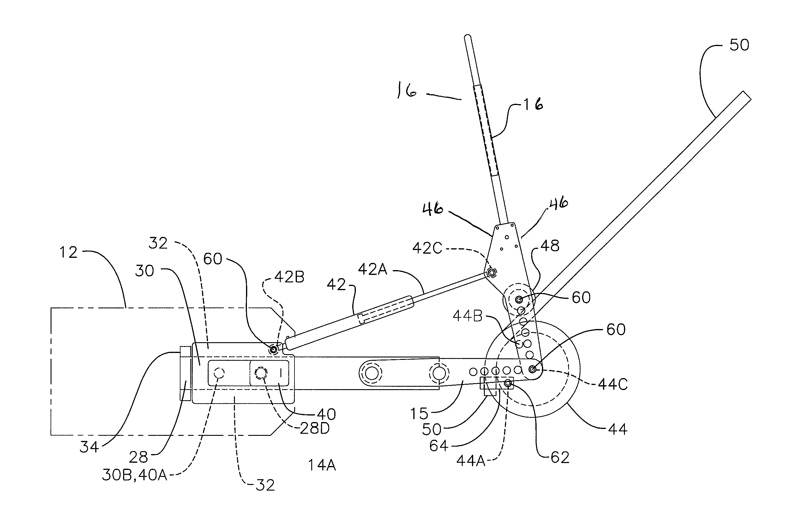
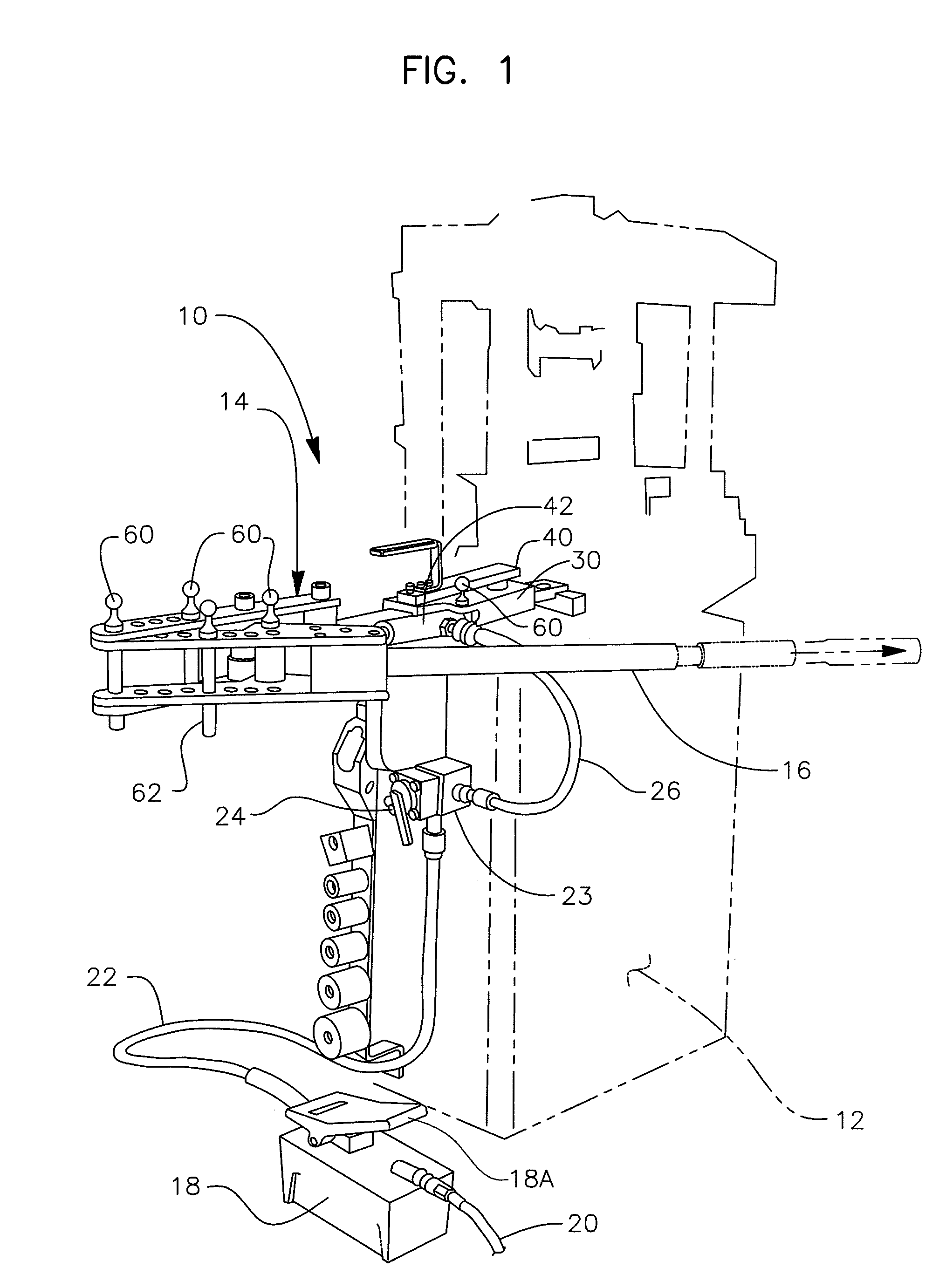
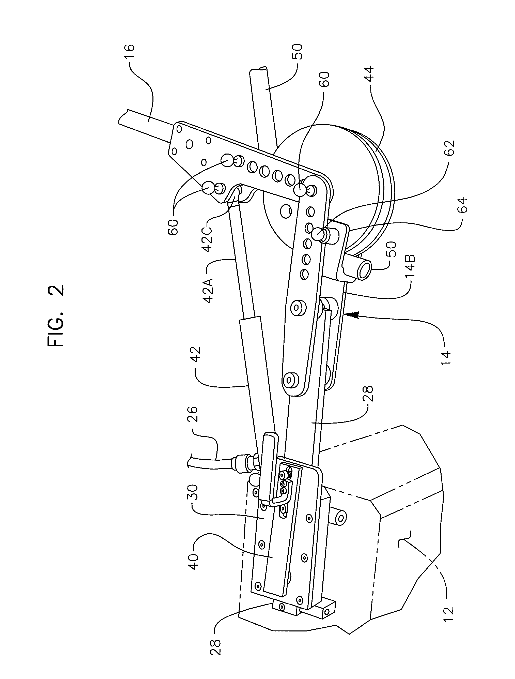
[0030]FIGS. 1-9 show details of the operating elements of apparatus 10 and arm 14 which supports the various elements. Apparatus 10 has means for connecting various bending elements or limit the range of operation of these elements. The elements are either connected or the range of bending operation determined by belaying pins 60 or flat sided belaying ins 62, described further later, both of which fit into the same size holes in a number of locations in apparatus 10 to permit attaching accessories which provide these various functions.

[0031]FIGS. 4-7 show the inner end of arm 14 which is attached to support 12. The inner portion of arm 14 consists of slide bar 28 which is oriented to guide slide 30 on a linear path from support 12. Slide bar 28 has planar surfaces. Slide 30 has planar surfaces with a pair of side plates 32 attached to its slide which extend downward over opposite sides of slide bar 28, each side plate having inwardly extending extensions 32A which grip the undersid...


PUM

PropertyMeasurementUnit
acute angleaaaaaaaaaa
angleaaaaaaaaaa
distanceaaaaaaaaaa

Abstract

Apparatus for bending stock to an acute angle. A hydraulic cylinder with a ram extendable under hydraulic pressure provides the bending power. The ram automatically retracts from an extended position when hydraulic pressure is removed. One end of an apparatus supporting arm consists of a slide bar. The slide bar end of the arm is secured to a support with the opposite end pivotably mounting a forming die and a lever. The lever pivotably mounts a forming roller. The lever carries the forming roller around the die and bend stock secured to the die around the die. A slide is slideably attached to the slide bar. The cylinder and ram are pivotably attached extending between the slide and the lever. With this arrangement providing hydraulic pressure to extend the ram will rotate the lever and forming roller around the die and bend secured stock around the die, then removing pressure will retract the ram and move the slide with the attached cylinder and ram towards the die where the slide is automatically locked in place. This permits making an acute angle bend by successive bends with the cylinder and ram at two different locations with respect to the die.

Description

FIELD OF THE INVENTION[0001]This invention relates to an improved apparatus for bending metal stock on the arc of a circle up to an acute angle of one hundred and eighty degrees.BACKGROUND OF THE INVENTION[0002]A large force is required to bend stock to an acute angle of one hundred and eighty degrees. Bending apparatus which requires such a large force uses a hydraulic cylinder with an extending ram. An extension of the ram transmits the force to apparatus which bears against the stock and bends it. An acute angle bend presents a problem compared to smaller bends because the force required is large and must be exerted over a long distance. This is difficult to achieve with a cylinder and ram because the long distance requires a long cylinder and ram which are both prone to buckling under such a large force.[0003]While a variety of metal stock benders are known in the art, the ability to bend stock to an acute 180 degree angle has only been provided by Mann et al. U.S. Pat. No. 2,65...

Claims


Application Information

Patent Timeline
Patent Type & Authority Patents(United States)
IPC IPC(8): B21D7/04B21D9/05B21J13/08
CPCB21D7/02
Inventor BULLE, MARSHALL R.
Owner BULLE MARSHALL R
Why Eureka
Try Eureka