Internal combustion engine and fuel injection method in internal combustion engine

a fuel injection method and internal combustion engine technology, applied in the direction of machines/engines, output power, electric control, etc., can solve the problems of undesired knocking, undesired misfire, undesired knocking, etc., and achieve the effect of reducing the amount of discharged nox and the amount of consumed fuel

Inactive Publication Date: 2009-05-26
HONDA MOTOR CO LTD
View PDF4 Cites 2 Cited by
  • Summary
  • Abstract
  • Description
  • Claims
  • Application Information

AI Technical Summary

Benefits of technology

[0009]With the above-described structural arrangement, the air-fuel ratio of the air-fuel mixture produced by the fuel injected from the first injector into the intake port or the combustion chamber is set in the range of 28 to 38. Therefore, when the temperature and pressure rise with the first combustion, which is started by spark-igniting the fuel injected from the second injector into the combustion chamber, the timing of starting the second compressive hypergolic ignition is optimized to provide a stable combustion state free of knocking and misfire. Thus, the present invention makes it possible to decrease an amount of discharged NOx and an amount of consumed fuel over a wide range of operating load.
[0015]With the above-described structural arrangement, the distance between the second injector and the spark plug is set at the value corresponding to ⅙ to ¼ of the inner diameter of the cylinder. Therefore, even if the timing of stopping the injection of fuel from the second injector is set to be later than that in the related art engine (JP '651) in order to decrease the amount of discharged NOx and the amount of consumed fuel, a sufficient penetration force of a fuel jet is secured, wherein the air-fuel ratio around the spark plug is sufficiently enriched to prevent misfire and unstable combustion from occurring.
[0017]With the arrangement of the above-discussed steps, the air-fuel ratio of an air-fuel mixture produced by the injected fuel from the first injector into the intake port or the combustion chamber is set in the range of 28 to 38. Therefore, when the temperature and pressure rise with the first combustion, which is started by spark-igniting the air-fuel mixture around the spark plug to the fuel injected from the second injector into the combustion chamber, the timing of starting the second compressive hypergolic ignition is optimized to provide a stable combustion state free of knocking and misfire. Thus, it is possible to decrease an amount of discharged NOx and an amount of consumed fuel over a wide range of operating load.

Problems solved by technology

However, in the engine disclosed by JP '651, the air-fuel ratio of the air-fuel mixture produced by the first fuel injection is not always appropriate.
Therefore, when the operating load is increased, an undesired knocking result occurs due to the enriched air-fuel ratio.
Also, when the operating load is decreased, an undesired misfire result occurs due to the lean air-fuel ratio without the compressive hypergolic ignition occurring.
Thus, the operating range of the engine disclosed by JP '651 is limited, resulting in the possibility of an insufficient decrease in the amount of discharged NOx and an insufficient decrease in the amount of consumed fuel occurring.

Method used


Image

  • Internal combustion engine and fuel injection method in internal combustion engine
  • Internal combustion engine and fuel injection method in internal combustion engine
  • Internal combustion engine and fuel injection method in internal combustion engine

Examples


Embodiment Construction

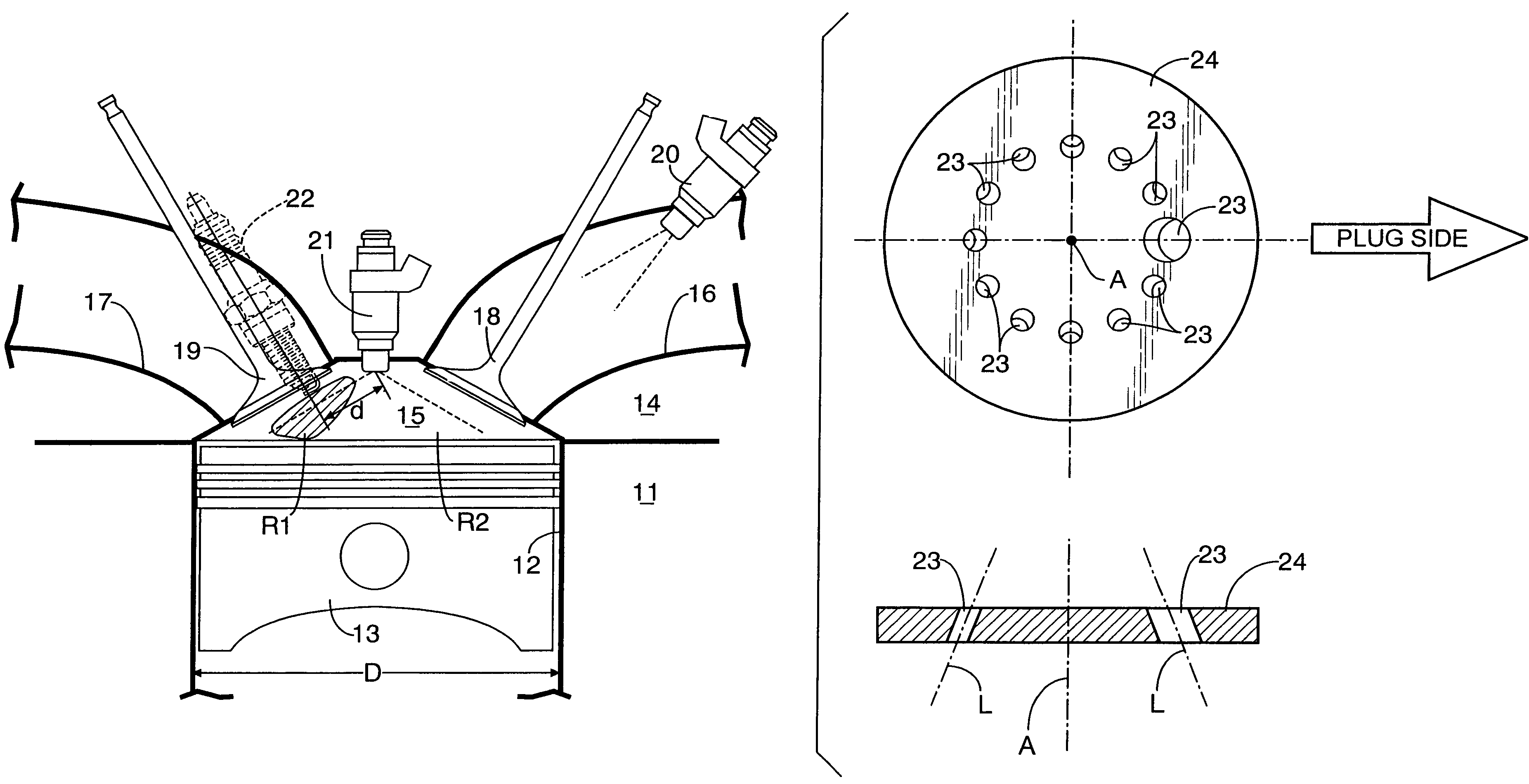
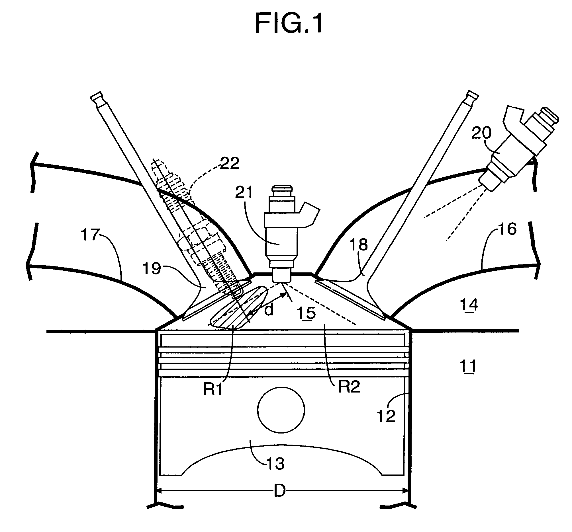
[0029]As shown in FIG. 1, an internal combustion engine according to the present invention includes a cylinder block 11, a piston 13 slidably received in a cylinder 12 formed in the cylinder block 11, and a combustion chamber 15 defined between an upper surface of the piston 13 and a lower surface of a cylinder head 14. An intake port 16 and an exhaust port 17 are formed in the cylinder head 14. An intake opening of the intake port 16 opening into the combustion chamber 15 is opened and closed by an intake valve 18. An exhaust opening of the exhaust port 17 opening into the combustion chamber 15 is opened and closed by an exhaust valve 19. A first injector 20 directed to the combustion chamber 15 is disposed at a position near the intake opening in the intake port 16. A second injector 21 is disposed at a central portion of a top of the combustion chamber 15 and extends along a cylinder axis. A spark plug 22 is disposed at a position near the exhaust valve 19 in the combustion chamb...


PUM


Abstract

An air-fuel ratio of an air-fuel mixture produced by fuel injected from a first injector into an intake port (or into a combustion chamber) is set in a range of 28 to 38. Therefore, when the temperature and pressure rise with a first combustion started by spark-ignition around a spark plug to the fuel injected from a second injector into the combustion chamber, the timing of starting a second compressive hypergolic ignition is optimized to provide a stable combustion state free of knocking and misfire.

Description

CROSS-REFERENCE TO RELATED APPLICATION[0001]The present invention claims priority under 35 USC 119 based on Japanese patent application No. 2006-345294, filed on Dec. 22, 2006. The entirety of the subject matter of this priority document is incorporated by reference herein.BACKGROUND OF THE INVENTION[0002]1. Field of the Invention[0003]The present invention relates to an internal combustion engine including: a first injector for injecting fuel into an intake port or a combustion chamber; a second injector for injecting the fuel into the combustion chamber following the injection of the fuel by the first injector; and a spark plug for igniting an air-fuel mixture within the combustion chamber, and also relates to a method of such fuel injection.[0004]2. Description of the Related Art[0005]Japanese Patent Application Laid-open No. 2003-49651 (JP '651) discloses a direct fuel-injection type engine that includes a spark plug and a fuel injection valve for directly injecting fuel into a ...

Claims


Application Information

Patent Timeline
Patent Type & Authority Patents(United States)
IPC IPC(8): F02B7/00F02B7/08
CPCF02B23/101F02D35/02F02D41/3023F02D41/3094F02M61/1826F02M61/1853F02M69/046F02B2023/103F02B2075/125F02B2275/16F02D13/0249Y02T10/125Y02T10/123F02D41/3041Y02T10/12
Inventor YAMADA, TAKUYAMORITA, TERUYOSHIISHITSUKA, YOSHIKAZUTAKEDA, NAOAKIUMEMOTO, ATSUSHIOGAWA, KENKIMURA, NORITAKAKOBAYASHI, TAKEO
Owner HONDA MOTOR CO LTD
Why Eureka
Try Eureka