
Drinking straw for heated liquids, method of cooling and combination with drinking vessels

a technology of drinking straw and heated liquid, which is applied in the direction of drawing-off water installations, tableware, construction, etc., can solve the problem of insufficient size of bubbles to effectively form

Inactive Publication Date: 2009-05-26
KOGAN GENNADY S
View PDF35 Cites 23 Cited by
  • Summary
  • Abstract
  • Description
  • Claims
  • Application Information

AI Technical Summary

Benefits of technology

[0011]Air-admitting orifices are provided in the tube wall below the expanded portion so that air is drawn into the straw through the orifices when a liquid is sucked through the straw. The air forms bubbles at the orifices which are entrained in the liquid being sucked through the straw. As the bubbles enter the expanded portion and region of lower pressure, the flow rate of the fluid slows down giving the bubbles time to enlarge and coalesce before being sucked as a foam into the user's mouth. Drinking straws in accordance with the present invention thus provide a method of delivering liquids such as coffee, tea, soup and the like to the user's mouth in hot, delicious form without risk of burning.
[0013]The plurality of expanded portions may be formed as a flexible joint that allow the outlet portion of the straw to articulate with respect to a portion of the straw on the other side of the joint. The tube wall may also be formed in telescoping sections. A first section including the outlet may have a larger diameter than a second section including the inlet with the expanded portions being formed in the lower end of the first section. As the second section is slid into the first section, the second section may selectively block the orifices in the expanded sections allowing a user to control the air / liquid proportion in the foam delivered to his or her mouth.
[0015]To minimize or prevent the liquid from leaking out of the drinking straw through the air-admitting orifices, the orifices may be sloped inwardly and downwardly such that the liquid tends to be drawn back into the tube when the user stops sucking and the liquid falls back down the tube. When the orifices are formed in a nipple, the nipples may be formed inside the tube or outside the tube.

Problems solved by technology

When such a straw is used with a hot liquid, the liquid is slightly cooled as it flows through the straw but it is still hot when it reaches a user's mouth and the bubbles are not large enough to effectively form a foam.

Method used


Image

  • Drinking straw for heated liquids, method of cooling and combination with drinking vessels
  • Drinking straw for heated liquids, method of cooling and combination with drinking vessels
  • Drinking straw for heated liquids, method of cooling and combination with drinking vessels

Examples


Embodiment Construction

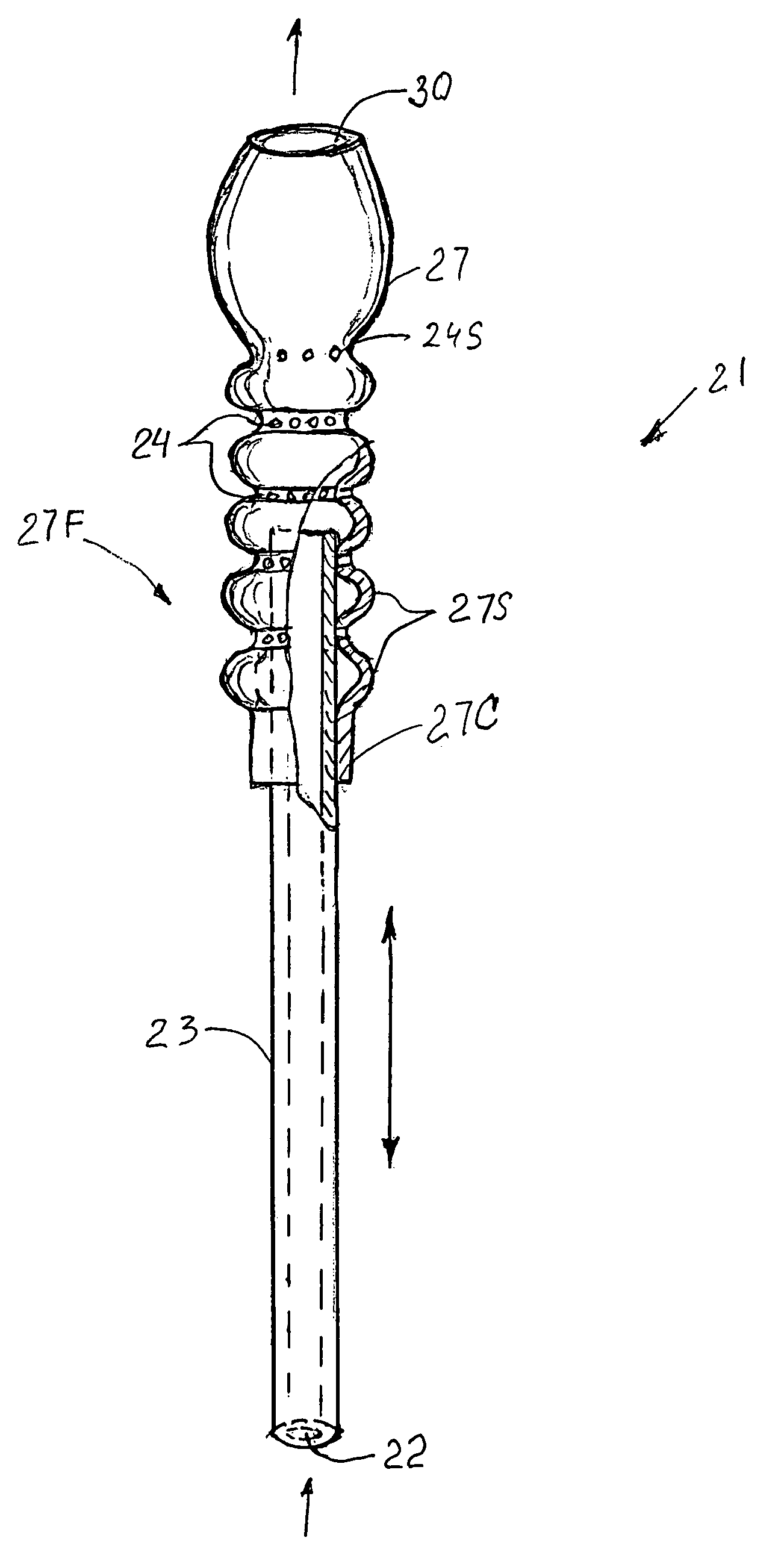
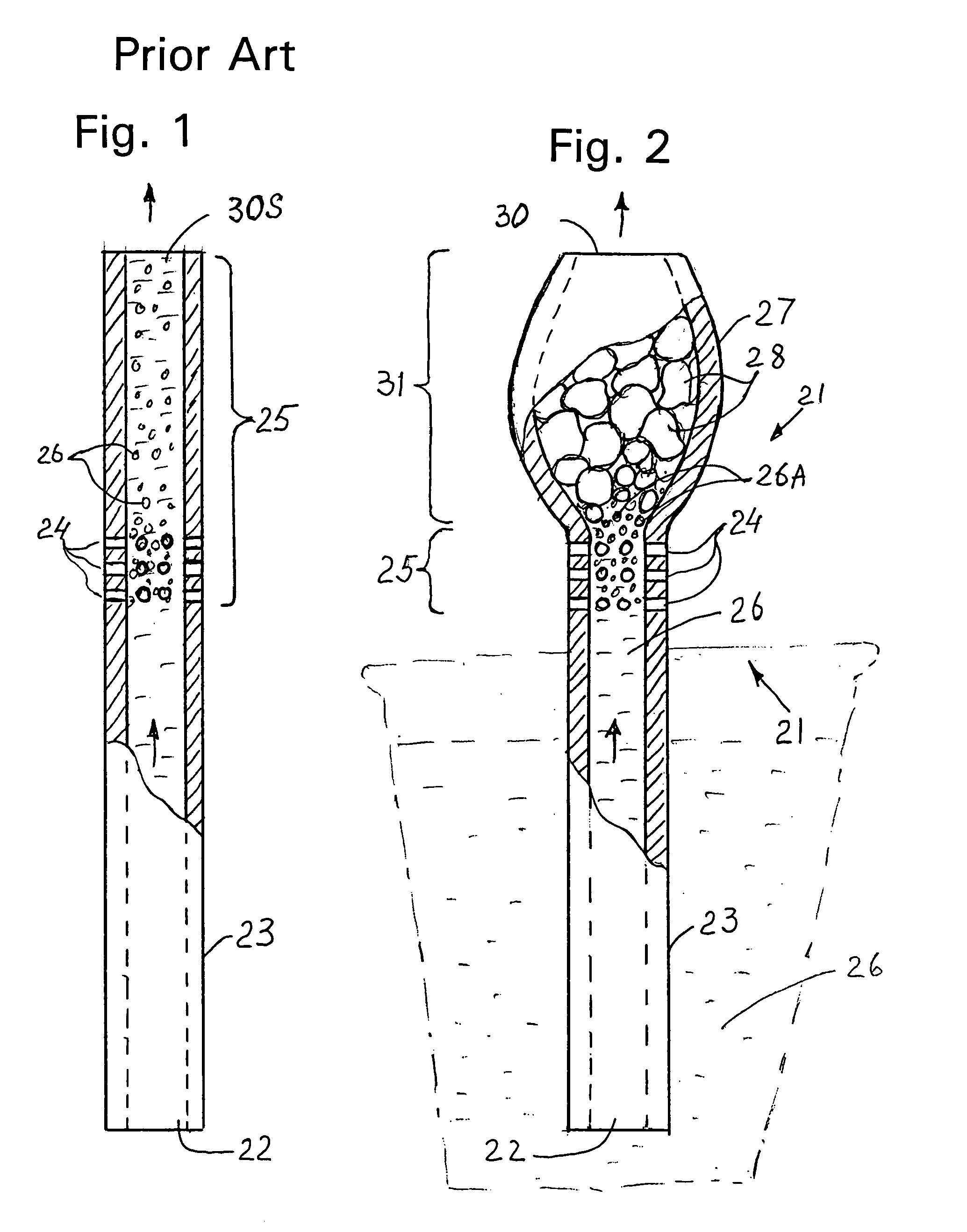
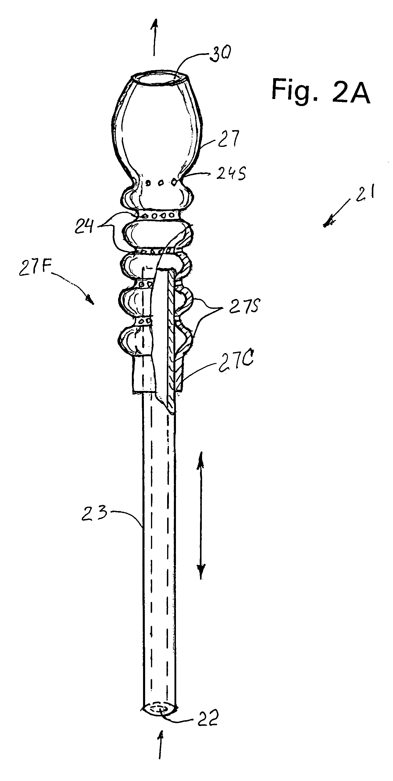
[0041]Referring to the drawings more particularly by reference character, as shown in FIG. 1 reference numeral 21 refers to a drinking straw in accordance with the present invention. Drinking straw 21 mainly comprises a hollow, continuous flow passage tube and includes the following connecting portions: A bottom portion 23 is intended for lowering into a drinking liquid. An area 25 includes air-admitting apertures 24 for bringing outside air into the drinking straw during suction. A top portion may perform a combination of two functions—namely, a bubble-expansion chamber and a mouthpiece.

[0042]A hot liquid 26 enters a drinking straw inlet 22 when a user applies suction and travels upwards to area 25. Upon entering area 25, outside air is pulled into the liquid through air-admitting apertures 24. The aerated liquid is then pulled into an area 31. Area 31 includes a chamber 27 that has a larger volume than portion 23 within area 25. The small bubbles 26A in chamber 27 are permitted to...


PUM


Abstract

A drinking straw for delivering a hot liquid in the form of a foam into a user's mouth that mimics the natural action of sucking in air for cooling the liquid. The straw has a tube wall with an expanded portion proximate an outlet. Air admitting orifices are provided in the tube wall below the expanded portion so that air is drawn into the straw through the orifices when a liquid is sucked through the straw. The straw may be used for cooling a hot liquid such as coffee, tea, soup or the like and may be used in connection with a container.

Description

[0001]This application claims priority from provisional application Ser. No. 60 / 687,726, filed Jun. 6, 2005, for Drinking Straw for Heated Liquids, Method of Cooling and Combination with Drinking Vessels.BACKGROUND OF THE INVENTION[0002]1. Field of the Invention[0003]The present invention relates to a drinking straw which delivers a hot liquid into the mouth of a user in the form of a foam and to a method wherein the hot liquid is cooled in the user's mouth as the foam collapses such that the mouth of the user is not burned. The drinking straw may be provided separately or in combination with a drinking vessel.[0004]2. Brief Description of the Prior Art[0005]To reduce the chance of burning the mouth, people instinctively sip a hot liquid. The sipping process mixes the hot liquid with air, thus creating an air-liquid mixture. The air keeps the liquid from burning the user's mouth while the liquid cools.[0006]Other than with the natural technique, inventive attention has been directed...

Claims


Application Information

Patent Timeline
Patent Type & Authority Patents(United States)
IPC IPC(8): A47G21/18
CPCA47G21/187
Inventor KOGAN, GENNADY S.
Owner KOGAN GENNADY S
Features
  • Generate Ideas
  • Intellectual Property
  • Life Sciences
  • Materials
  • Tech Scout
  • Unparalleled Data Quality
  • Higher Quality Content
  • 60% Fewer Hallucinations
Learn More