Crank Trigger Distributor

a distributor and crank trigger technology, applied in the direction of manufacturing tools, machines/engines, mechanical equipment, etc., can solve the problems of affecting the quality of crank trigger distributors, and the inability of lower drive gear to properly mesh with cam gear, so as to facilitate adjustment to different intake manifold heights and optimize gear meshing

Inactive Publication Date: 2013-04-18
MOROSO PERFORMANCE PRODS
View PDF11 Cites 0 Cited by
  • Summary
  • Abstract
  • Description
  • Claims
  • Application Information

AI Technical Summary

Benefits of technology

[0034]Other embodiments of the invention allow for a distributor that is threaded and has an adjustable billet collar that easily adjusts to different intake manifold heights to optimize gear meshing. The collar may have an integrated hold-down.
[0035]Other embodiments of the invention allow for the sealing flange to feature an O-ring and gasket used to seal crankcase vacuum regardless of the collar height. Such O-rings may be thick O-rings that can withstand frequent installation and removal.
[0036]Other embodiments of the invention allow for adjusting rotor tip phasing without touching the distributor hold-down as the cap itself can be adjusted. Other embodiments allow for the rotor tip not having to be rephrased after removing and reinstalling the distributor. Other embodiments may involve adjusting the cap to adjust rotor phasing and / or timing.

Problems solved by technology

Existing crank trigger distributors suffer from various deficiencies.
One such deficiency is that crank trigger distributors typically leak vacuum through the distributor installation hole in the intake manifold.
Other such deficiencies involve not being easily adjustable, so that the lower drive gear cannot properly mesh with the cam gear, without the crank trigger distributor being adjusted.
This makes it difficult to design distributors that can be adapted to engine blocks or intake manifolds of various manufacturers.
Furthermore, existing distributors are not both adjustable while also maintaining the positive seal to control crankcase vacuum.
The deficiencies of current crank trigger distributors is especially significant in automobile or truck racing engines as existing crank trigger distributors do not allow for a proper seal that prevents crankcase leakage when the engine builder is attempting to create a vacuum in the crankcase for increased horsepower.
However, none of these existing systems provide a distributor that prevents crankcase leakage, while being adjustable and adaptable to engine blocks or intake manifolds of various manufacturers.

Method used


Image

  • Crank Trigger Distributor
  • Crank Trigger Distributor
  • Crank Trigger Distributor

Examples


Embodiment Construction

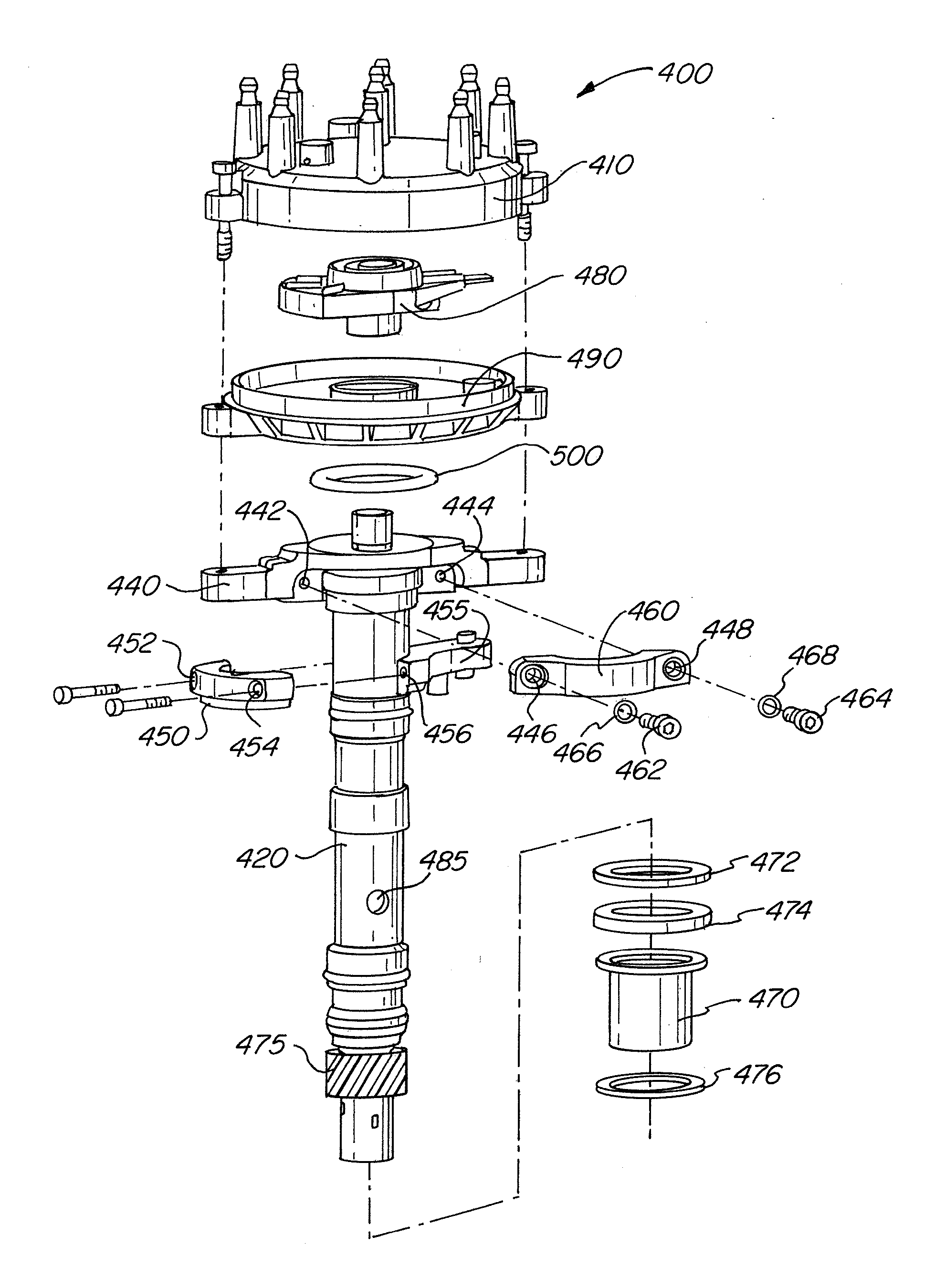
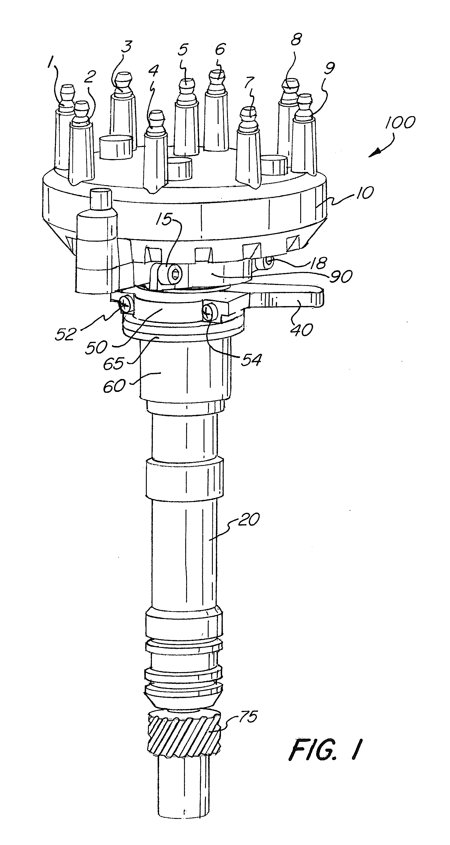
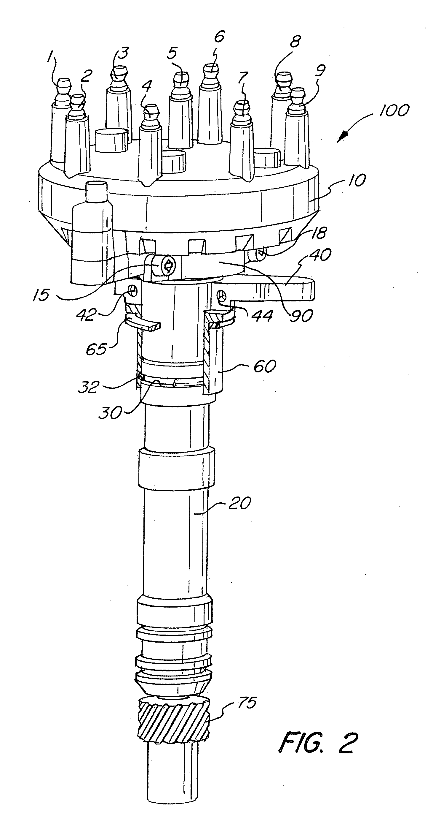
[0048]Referring to FIG. 1, crank trigger distributor 100 of the present invention is shown. Here, distributor 100 is shown with distributor stem 20 and cap 10. Cap 10 is connected to the distal end of the distributor stem. Also shown is collar 40 / 50, and sealing flange (sealing element) 60. Crank trigger distributor 100 also has sealing gasket 65 and timing adjustment clamp 90. Timing adjustment clamp 90 is held in place by fasteners, shown as screws 15 and 18. The fasteners may be other fasteners known in the art other than screws.

[0049]Collar 40 / 50 shown in FIG. 1 comprises two mating parts: part 40 and part 50. Screws 52 and 54 are shown connecting part 40 to part 50, where these parts extend radially around distributor stem 20. Furthermore, cap 10 is shown having various spark plug style terminals 1-9. There is a rotor (not shown) inside the distributor.

[0050]At the proximal end of distributor stem 20 of FIG. 1, a gear 75 is shown. Washers (not shown) may be attached to the prox...


PUM

PropertyMeasurementUnit
heightsaaaaaaaaaa
heightaaaaaaaaaa
voltageaaaaaaaaaa

Abstract

A crank trigger distributor assembly and method for sealing the crankcase from leaking vacuum through the distributor installation hole. A crank trigger distributor assembly and method for minimizing and/or preventing crankcase leakage, while being adjustable and adaptable to engine blocks or intake manifolds of various manufacturers. A crank trigger having a distributor stem, a collar located on the distributor stem, and at least one sealing element, the at least one sealing element incorporated within the collar. A crank trigger distributor assembly and method for adjusting rotor tip phasing without touching the distributor hold-down, as the cap itself can be adjusted.

Description

FIELD OF THE INVENTION[0001]This invention relates to a crank trigger distributor assembly and method for sealing the crankcase from leaking vacuum through the distributor installation hole in the intake manifold.BACKGROUND OF THE INVENTION[0002]A distributor is a device in the ignition system of an internal combustion engine that routes voltage from an ignition coil to the spark plugs in the correct firing order. Crank trigger distributors are a specialized subset of distributors that are designed for racing engines that use a crankshaft triggered ignition. Their low profile lets them fit in tight quarters and still accurately deliver the sparks required for ignition.[0003]Crank trigger distributors, and distributors in general, have a rotating arm or rotor inside the distributor cap, on top of the distributor shaft, that is insulated from the shaft and the body of the vehicle (ground). The distributor shaft is driven by a gear on the camshaft. The metal part of the rotor typically...

Claims


Application Information

Patent Timeline
Patent Type & Authority Applications(United States)
IPC IPC(8): F02P7/04H01R39/02B23P11/00
CPCY10T29/49231F02P7/04
Inventor SCALIA, VINCENT P.
Owner MOROSO PERFORMANCE PRODS
Why Eureka
Try Eureka