Pressure relief valve

a pressure relief valve and valve body technology, applied in the field of pressure relief valves, can solve the problems of preventing the valve from maintaining the desired pressure seal, and causing premature and/or undesirable leakage of prior art pressure relief valves, so as to prevent or minimize leakage, minimize and/or prevent leakage, the effect of preventing or minimizing leakag

Active Publication Date: 2013-08-13
DRESSER LLC
View PDF27 Cites 2 Cited by
  • Summary
  • Abstract
  • Description
  • Claims
  • Application Information

AI Technical Summary

Benefits of technology

[0007]In some implementations, the PRV of the present disclosure includes a disc-nozzle combination that minimizes and / or prevents process fluid leakage therethrough by deflection of portions of the disc and / or nozzle due to a thermal gradient between the process fluid temperature and the ambient condition. For example, in some implementations, the disc of the PRV may include a groove disposed on an outer circumferential surface of the disc, thereby forming a protrusion (e.g., a lip) that deflects axially (rather than or in addition to radially) in order to sealingly contact the nozzle (as explained more fully below). Further, in some implementations, the nozzle may include a notch disposed in an exterior circumferential surface of the nozzle to form a protrusion (e.g., a ledge) that, in response to a thermal gradient between the process fluid and the ambient condition on the outlet of the PRV, said ledge deflects to sealingly contact the disc and minimize and / or prevent leaks.
[0008]Various implementations of a pressure relief valve (PRV) according to the present disclosure meet long felt but unmet needs for valves in cryogenic service. PRVs of the present disclosure may include one or more of the following features. For example, the PRV may help prevent or minimize leaks during cryogenic service of the valve. In some implementations, the PRV may help prevent or minimize such leaks subsequent to a first opening (or “pop”) of the valve in use in cryogenic service. As another example, the PRV may be used in a wide variety of cryogenic services and fluid temperatures while minimizing and / or preventing leaks through the valve caused at least in part by a temperature difference between the process fluid circulating through the valve and an ambient temperature condition in the valve (e.g., temperature on an outlet side of the PRV). As another example, the PRV may maximize set tightness during cryogenic service of the valve. The PRV may also utilize thermal characteristics of a material used for a valve disk and / or nozzle to minimize and / or prevent leaks of the valve during cryogenic service. For instance, the PRV may utilize a material deflection caused by a thermal gradient across the disc and / or nozzle to minimize and / or prevent leaks between the disk and nozzle. In sonic cases, the PRV may utilize the thermal characteristics with a geometry of the disc and / or nozzle in order to minimize and / or prevent leaks between the disc and nozzle. For example, one or more components of the PRV may axially deflect, rather than radially deflect, to sealingly contact and close the PRV to fluid flow therethrough in order to minimize and / or prevent leaks of the process fluid through the PRV.

Problems solved by technology

In some instances, premature and / or undesirable leaks from prior art pressure relief valves may occur due in part to a difference in temperature between a fluid flowing to an inlet of the pressure relief valve and an ambient condition within the valve.
Such a leak may begin as a microleak but, without attention, may increase in flow to a macroleak, thereby preventing the valve from maintaining a desired pressure-seal in the system.
Very large temperature differences may occur with valves in cryogenic service.
Such prior art valve discs may also experience galling.
In some cases, galling is a form of surface damage on an interior surface of the pressure relief valve arising between sliding solids.
Galling may contribute or exacerbate the leaks experienced by the pressure relief valve due to the temperature difference experienced in cryogenic service.

Method used


Image

  • Pressure relief valve
  • Pressure relief valve
  • Pressure relief valve

Examples


Embodiment Construction

[0020]Reference is now made to the drawings wherein like reference characters indicate like or similar parts through the figures.

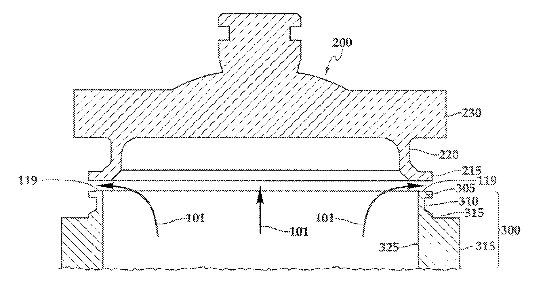
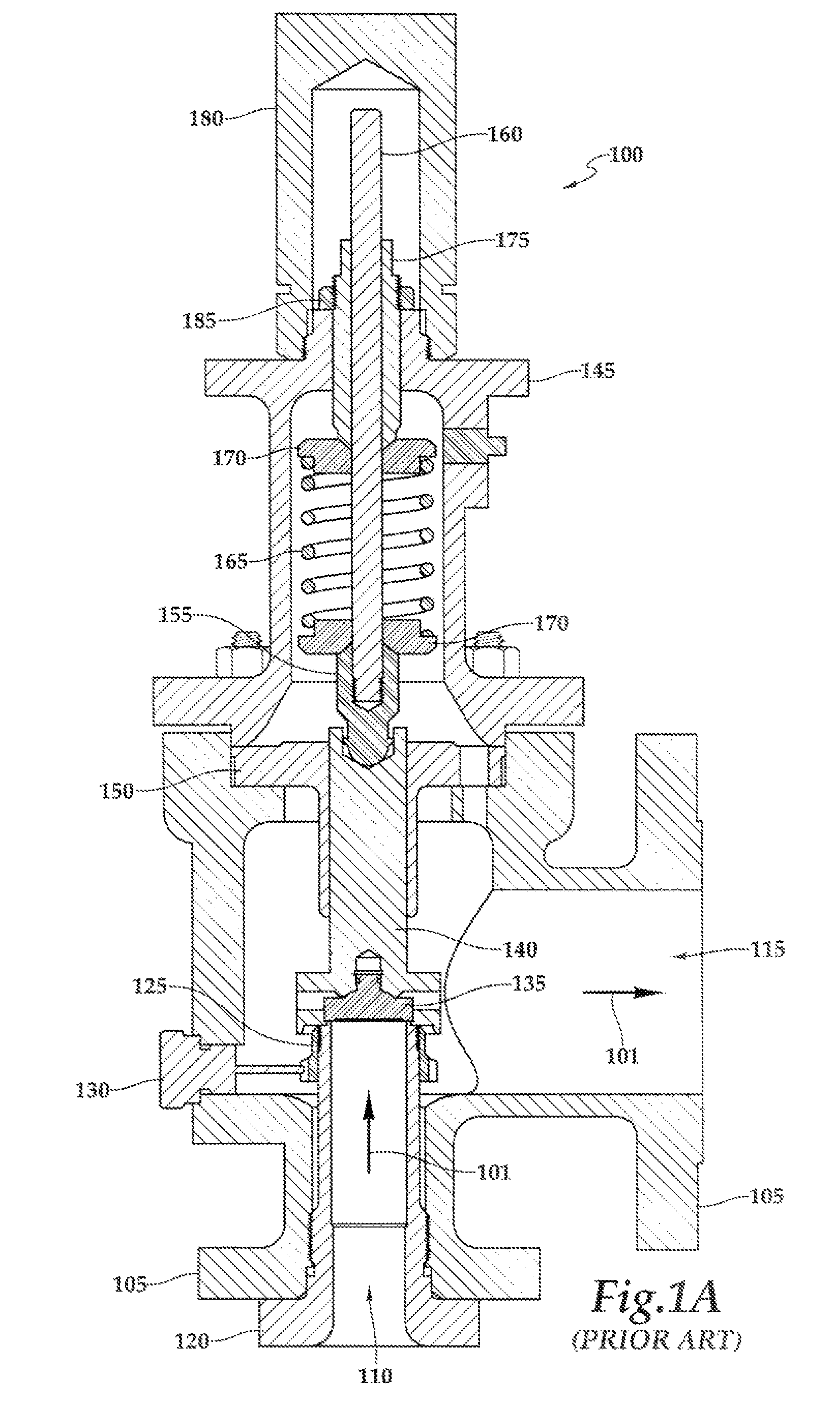
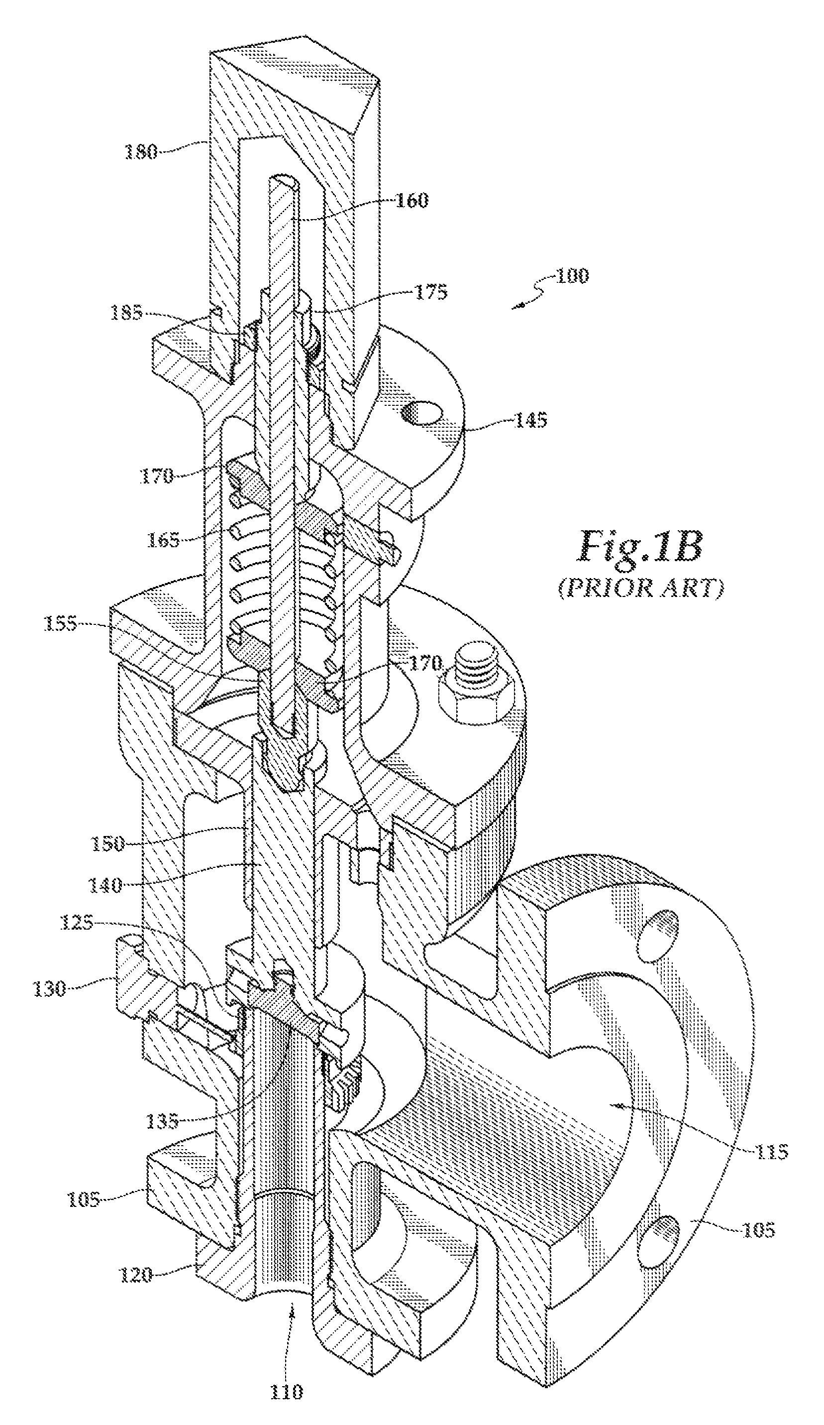
[0021]A pressure relief valve (PRV) according to the present disclosure may include a disc, a disc holder, a nozzle, and a mass-spring-damper system that allows for a fluid (e.g., gas, liquid, or multiphase fluid) within a system, such as a piping system or pressure vessel, to be relieved by operation of the PRV when the fluidic, pressure of the fluid exceeds a predetermined threshold. In some embodiments, the PRV may be used for cryogenic service, where a process fluid circulated to the PRV is at a lower temperature than an ambient condition at an outlet of the PRV. “Cryogenic service,” when used in the present disclosure, refers to applications in which a temperature of the process fluid circulated to the PRV is within one of the following temperature ranges: −21 to −75 F (e.g., propane as the process fluid); −76 to −150 F (e.g., ethylene as the process ...


PUM


Abstract

A pressure relief valve for cryogenic service includes: a fluid inlet and a fluid outlet; a nozzle disposed within the fluid inlet, said nozzle having a nozzle groove radially formed on an exterior cylindrical surface of the nozzle and an outwardly disposed ledge having a lower ledge surface comprising a portion of an exterior surface of the nozzle groove and an upper ledge surface comprising a seat; a substantially cylindrical closure disc with a lower portion including a groove formed on an exterior radial surface of the cylindrical body, an outwardly disposed lip having an upper surface comprising a portion of an interior surface of the groove, said lip of the closure disc having a lower closure surface. The lip of the closure disc being adapted to deflect downward and inward in response to a cryogenic thermal gradient applied across the lip.

Description

TECHNICAL BACKGROUND[0001]This disclosure relates to pressure relief valves, and more particularly, to pressure relief valves suitable for use in cryogenic applications.BACKGROUND[0002]Typically, a pressure relief valve may be used to control or limit pressure in a system or vessel, which can build up by, for example, a process upset, instrument or equipment failure, or fire. In some instances, pressure relief valves may be used in a chemical processing plant that distills natural gas into pure methane, e.g., a “methanizer.” The process eliminates impurities like toluene and ethane from the natural gas to provide pure methane. The distillation is done by the adiabatic expansion of natural gas. Pressurized natural gas is made to work on compressors. The reduction in pressure to perform work is reflected by a drop in temperature. At different stages of temperature drops, the different compounds, such as toluene and ethane, start distilling and are collected in separate containers. Sin...

Claims


Application Information

Patent Timeline
Patent Type & Authority Patents(United States)
IPC IPC(8): F16K17/20
CPCF16K1/36F16K17/003F16K31/002Y10T137/0324Y10T137/7737Y10T137/7746
Inventor KRITHIVASAN, RAJESH
Owner DRESSER LLC
Why Eureka
Try Eureka