Sheet conveying apparatus, image forming apparatus, and image reading apparatus

a conveying apparatus and a technology for reading apparatus, applied in the field of conveying apparatus, image forming apparatus, and image reading apparatus, can solve the problems of deteriorating correcting precision, skewing cannot be corrected, and the time required for registration becomes long, and achieves the effect of increasing the size of the apparatus

Inactive Publication Date: 2009-05-26
CANON KK
View PDF10 Cites 12 Cited by
  • Summary
  • Abstract
  • Description
  • Claims
  • Application Information

AI Technical Summary

Benefits of technology

[0023]The invention is made in consideration of such circumstances and it is an object of the invention to provide a sheet conveying apparatus, an image forming apparatus, and an image reading apparatus in which skew correcting precision of a sheet can be improved without increasing a size of the apparatus.

Problems solved by technology

However, since the foregoing loop registration system has the construction in which the deflection is formed in the sheet and the skew of the sheet is corrected by the elasticity of the sheet, in other words, the sheet is temporarily stopped and the skew of the sheet is corrected, a time which is required for the registration becomes long.
If “conveying load of the sheet>conveying force of the skew correcting roller”, the skew cannot be corrected.
Even in the case near such a relation, a slip occurs between the sheet and the skew correcting roller and the skew correction is insufficient, thereby deteriorating the correcting precision.
However, since a rigidity of thick paper is large, the repulsion of the deflection increases and the conveying load increases, thereby further deteriorating the skew correcting precision.
However, in such conventional sheet conveying apparatus and image forming apparatus, there is such a tendency that even when the conveying roller pair which is moved in the lateral direction is provided, in recent years, if a variety of many types of sheets are used, the conveying load cannot be sufficiently reduced and the skew correcting precision deteriorates.
If the contact pressure of the skew correcting roller pair increases as mentioned above, not only the durability deteriorates but also a large torque is necessary, causing an increase in motor size.
Thus, the costs increase and the apparatus size increases.

Method used


Image

  • Sheet conveying apparatus, image forming apparatus, and image reading apparatus
  • Sheet conveying apparatus, image forming apparatus, and image reading apparatus
  • Sheet conveying apparatus, image forming apparatus, and image reading apparatus

Examples


first embodiment

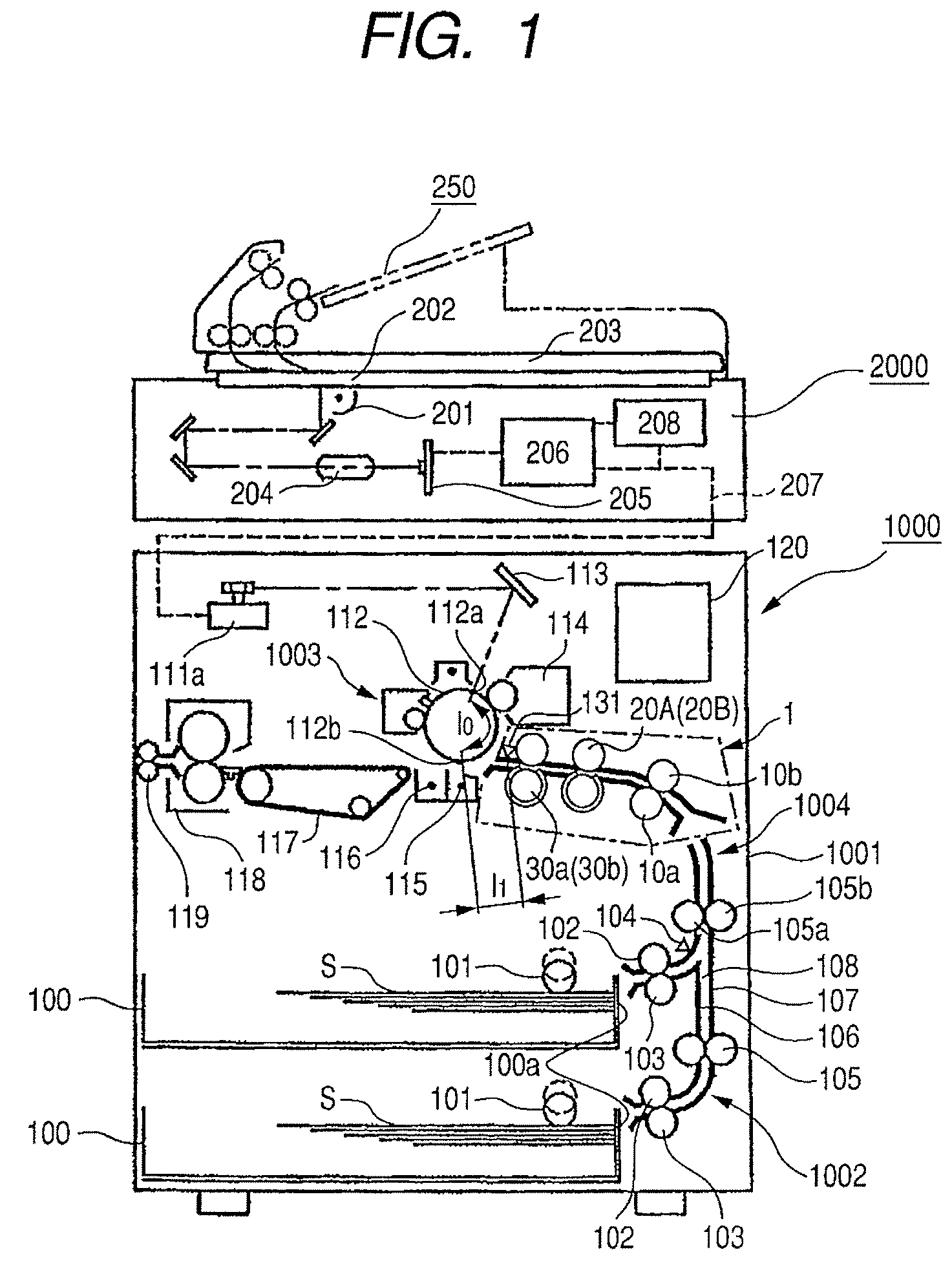
[0038]FIG. 1 is a schematic constructional diagram of a printer as an example of an image forming apparatus having a sheet conveying apparatus according to the invention.

[0039]In FIG. 1, a printer 1000 has: a printer main body 1001; and a scanner 2000 arranged on an upper surface of the printer main body 1001.

[0040]The scanner 2000 for reading an original document (hereinbelow, also referred to as an original) has: a scanning optical system light source 201; platen glass 202; and an original pressing plate 203 which is freely opened and closed. The scanner 2000 also has: a lens 204; a photosensing element (photoelectric conversion) 205; an image processing unit 206; a memory unit 208 for storing an image processing signal processed by the image processing unit 206; and the like.

[0041]When the original is read, light is irradiated from the scanning optical system light source 201 onto the original (not shown) put on the platen glass 202. The read original image is processed by the im...

second embodiment

[0087]the invention in which the conveying roller pair is moved in the direction which perpendicularly crosses the conveying direction at the time of such a skew correcting operation of the sheet will now be described.

[0088]FIG. 7 is a diagram for illustrating a construction of a registration roller unit of a sheet conveying apparatus according to the second embodiment. In FIG. 7, the same and similar component elements as those in, for example, FIG. 3 are designated by the same reference numerals.

[0089]In FIG. 7, a conveying roller pair 11 can be moved in the lateral direction. A moving motor M4 moves the conveying roller pair 11 in the lateral direction. A conveying driving motor M5 rotates the conveying roller pair 11.

[0090]In the embodiment, control is made so as to move the conveying roller pair 11 in the lateral direction synchronously with the operation of the skew correcting roller pairs (20A, 20B). It is assumed that a movement control amount and a control speed of the conv...

third embodiment

[0094]the invention will now be described.

[0095]FIG. 8 is a perspective view for illustrating a construction of a registration roller unit of a sheet conveying apparatus according to the third embodiment. FIG. 9 is a side elevational view of FIG. 8. In FIGS. 8 and 9, the same and similar component elements as those in, for example, FIG. 3 are designated by the same reference numerals.

[0096]In FIGS. 8 and 9, a roller 313 is rotatably attached to the guiding surface of the inside center-guiding portion 306. By providing such a roller 313, a slide frictional resistance between the sheet S and the inside center-guiding portion 306 is reduced. Thus, the skew correcting precision can be improved and it is possible to prevent the sheet S from being damaged in a slide frictional portion.

[0097]Although the example in which the roller 313 is provided for the inside center-guiding portion 306 has been shown in FIGS. 8 and 9, one or a plurality of rollers 313 can be also provided for the guidin...


PUM

PropertyMeasurementUnit
sizeaaaaaaaaaa
elasticityaaaaaaaaaa
distanceaaaaaaaaaa

Abstract

A curved conveying guiding portion which guides a sheet toward a skew correcting unit is provided on a sheet conveying direction upstream of the skew correcting unit which corrects a skew of the sheet by rotating the sheet while conveying it. By narrowing an interval in the vertical direction in a center portion in the lateral direction of the conveying guiding portion, when a sheet S is rotated and corrected by the skew correcting unit, a load which the sheet to be corrected receives from the conveying guiding portion is reduced.

Description

BACKGROUND OF THE INVENTION[0001]1. Field of the Invention[0002]The present invention relates to a sheet conveying apparatus, an image forming apparatus, and an image reading apparatus and, more particularly, to a construction for correcting a skew of a sheet such as recording paper, original document, or the like which is conveyed to one of an image forming unit and an image reading unit.[0003]2. Description of the Related Art[0004]Hitherto, an image forming apparatus or an image reading apparatus such as copying apparatus, printer, or facsimile apparatus has a sheet conveying apparatus for conveying a sheet such as recording paper, or original document (hereinbelow, also referred to as an original) to an image forming unit or an image reading unit. The sheet conveying apparatus has a skew correcting unit for correcting a skew of the sheet in order to correct a posture of the sheet or adjust a position of the sheet until it is conveyed to the image forming unit or the image reading...

Claims


Application Information

Patent Timeline
Patent Type & Authority Patents(United States)
IPC IPC(8): B65H9/00
CPCB65H5/38B65H9/002B65H2301/331B65H2404/611
Inventor KAWAGUCHI, DAISUKE
Owner CANON KK
Why Eureka
Try Eureka