Tool holding device

a tool and tool technology, applied in the field of tool holding devices, can solve the problems of frequent replacement of tools, large replacement costs, shortening the life of tools, etc., and achieve the effects of reducing replacement times, enhancing connection strength between the base and the block, and reducing tool li

Active Publication Date: 2009-05-26
EVERPADS
View PDF3 Cites 47 Cited by
  • Summary
  • Abstract
  • Description
  • Claims
  • Application Information

AI Technical Summary

Benefits of technology

[0007]It is therefore an aspect to provide a tool holding device to enhance the counterforce bearing of the shoulder wall and the countering wall by clamping the block within the receiving portion with a non-obtuse angle.
[0008]It is therefore another aspect to provide a tool holding device to reinforce the connection strength between the base and the block through the protrusion embedded within the track in the form of a dovetail, and the retaining portion of the block obstructed against the surface of the base.
[0009]It is therefore another aspect to provide a tool holding device wherein the groove conducts the fragments during the operation to prevent them from getting stuck and deteriorating the performance of the chisel.
[0013]As a result, the tool holding device of the present invention has greater mechanical strength wherein the connection strength between the base and the block is also enhanced. Accordingly, the replacement times are decreased and the material cost is also reduced.

Problems solved by technology

In addition, the tough processed material shortens the lifetime of the tool and results in frequent replacements of the tool.
However, the counterforce resulting from the operation is stressed on both the base and the block such that extensive replacement and large costs arise because of the inferior tightness between the base and the block.
Because the counterforce resulting from the operation of the road planer is stressed on both the base and the block, the block may wear out or even break after a long operation period.

Method used


Image

  • Tool holding device
  • Tool holding device
  • Tool holding device

Examples


first embodiment

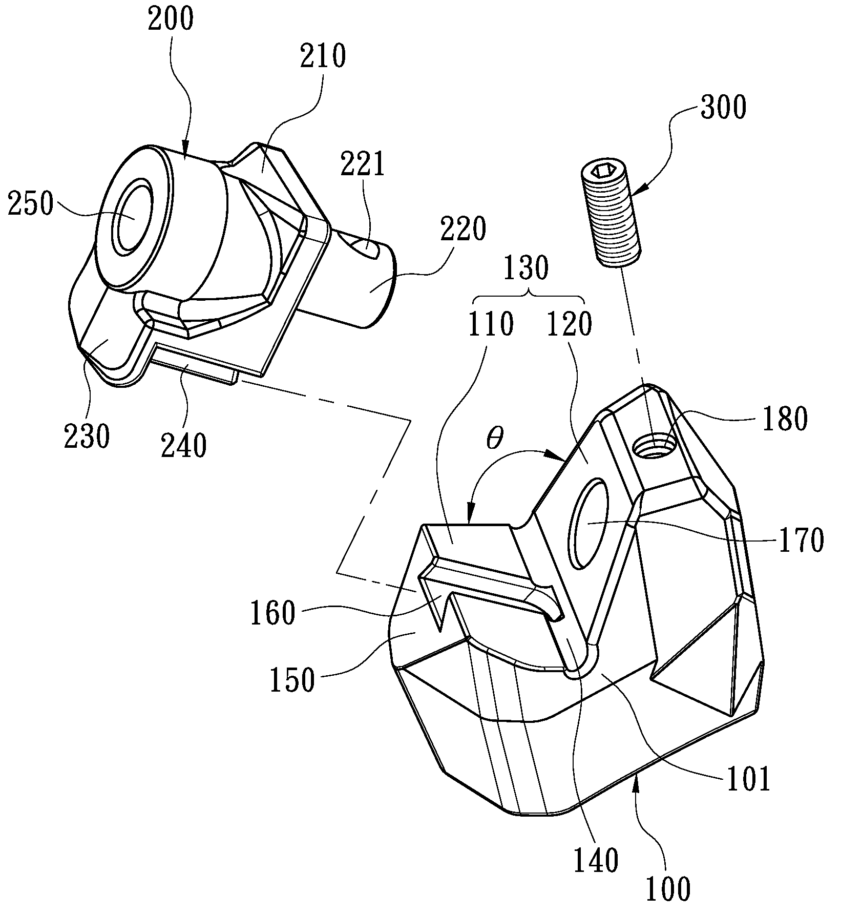
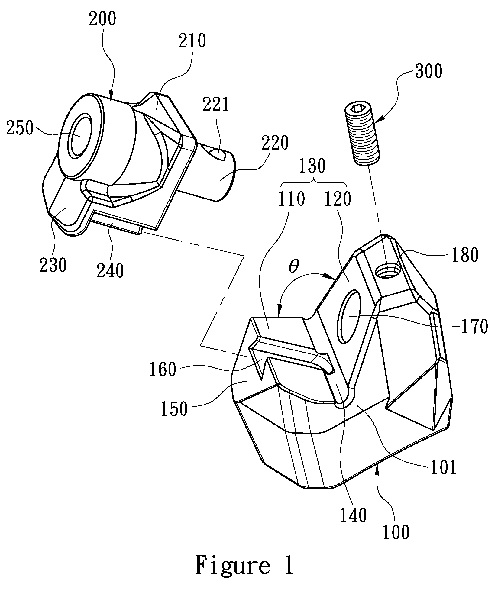
[0024]Refer to FIG. 1 and FIG. 2. FIG. 1 illustrates an exploded view of the tool holding device in accordance with the present invention; FIG. 2 illustrates a perspective view of the tool holding device in accordance with FIG. 1.

[0025]The tool holding device includes a base 100, a block 200 and a fastening member 300. The tool holding device is fixed on a roller 510 of a road planer 500 to receive a chisel 400 to dig and mill the road surface (shown in FIG. 5).

[0026]Refer to FIG. 1, FIG. 3 and FIG. 5. FIG. 3 illustrates a sectional view of the tool holding device in accordance with FIG. 2; FIG. 5 illustrates an operating schematic view of the tool holding device of the first embodiment.

[0027]The bottom of the base 100 is welded on a peripheral surface 511 of the roller 510 in accordance with the curve of the roller 510. The base 100 includes a receiving portion 130, a groove 140, a surface 150, a track 160, a penetrated hole 170 and a positioning hole 180. The receiving portion 130...

second embodiment

[0034]The tool holding device of the second embodiment includes a base 600, a block 700, a sleeve 800, and a fastening member 900. The tool holding device is fixed on a roller 510 of a road planer 500 to receive a chisel 400 to dig and mill the road surface.

[0035]The bottom of the base 600 is welded on a peripheral surface 511 of the roller 510 in accordance with the curve of the roller 510. The base 600 includes a receiving portion 630, a groove 640, a surface 650, a track 660, a penetrated hole 670 and a positioning hole 680. The receiving portion 630 is defined between a shoulder wall 610 and a countering wall 620. The groove 640 is formed on a junction between the shoulder wall 610 and the countering wall 620, and communicating with the opposite flanks 601 of the base 600. The surface 650 is defined adjacent to the shoulder wall 610 perpendicularly and away from the countering wall 620. The track 660 is formed on the shoulder wall 610 in a dovetail formation. The penetrated hole...


PUM

PropertyMeasurementUnit
angleaaaaaaaaaa
non-obtuse angleaaaaaaaaaa
lifetimeaaaaaaaaaa

Abstract

A tool holding device is disclosed, and the tool holding device includes a base, a block, and a fastening member for securing the block. The base includes a receiving portion defined between a countering wall and a shoulder wall, a surface defined adjacent to the shoulder wall perpendicularly and away from the countering wall, a penetrated hole defined on the countering wall, and a positioning hole communicating with the penetrated hole. The block includes a holding portion held in the receiving portion, a handle received in the penetrated hole, and a holding hole for holding a chisel. The countering wall and the shoulder wall define an angle less than or equal to 90 degrees. Therefore, the counterforce bearing of the base and block are both enhanced to raise the strength of the tool holding device.

Description

BACKGROUND[0001]1. Field of Invention[0002]The present invention relates to a holding device, and more particularly a tool holding device for a road planer.[0003]2. Description of Related Art[0004]A cutter holder and a tool holding device for the road planer are shown in EP 1761682 and US 2006 / 0119165. The cutter holder and the tool holding device respectively include a base and a block wherein the base is welded on the peripheral surface of the working member (ex. roller) and the block is secured on the base through a fastening member to receive a tool (such as a chisel). The tool received in the block is located along a tangent of the roller to dig into the earth for planning, excavating or milling operation.[0005]When the road planer works, the tool bit is forced to drill and excavate as the roller rotates such that the processed material (such as concrete and asphalt) coated on the road surface can be removed. In addition, the tough processed material shortens the lifetime of th...

Claims


Application Information

Patent Timeline
Patent Type & Authority Patents(United States)
IPC IPC(8): E21C35/193
CPCB28D1/188E21C35/19E21C35/193
Inventor CHIANG, CHUN-LI
Owner EVERPADS
Why Eureka
Try Eureka