Illumination optical system and exposure apparatus including the same

an optical system and exposure apparatus technology, applied in the field of illumination optical systems, can solve the problems of not being able to achieve the effect of suppressing distortion and good illumination

Inactive Publication Date: 2009-05-26
CANON KK
View PDF6 Cites 52 Cited by
  • Summary
  • Abstract
  • Description
  • Claims
  • Application Information

AI Technical Summary

Benefits of technology

[0014]The present invention provides an illumination optical system capable of further suppressing distortion in the effective light source shape observed therein and thus realizing good illumination.

Problems solved by technology

Light of the extreme ultraviolet region is largely absorbed by substances, and is therefore not practical for use with dioptric systems constituted mainly by lenses.
However, as a result of reviews by the present inventors, it has been found that the illumination optical system of Japanese Patent Laid-Open No. 2005-141158 still has some distortion in the effective light source shape and that the degree of this distortion is not negligible.
As described above, since the illumination optical system disclosed in Japanese Patent Laid-Open No. 2005-141158 still has a slight distortion in the effective light source shape, it has become impossible for this system to accommodate recent demands for higher image-forming performance.

Method used


Image

  • Illumination optical system and exposure apparatus including the same
  • Illumination optical system and exposure apparatus including the same
  • Illumination optical system and exposure apparatus including the same

Examples


first embodiment

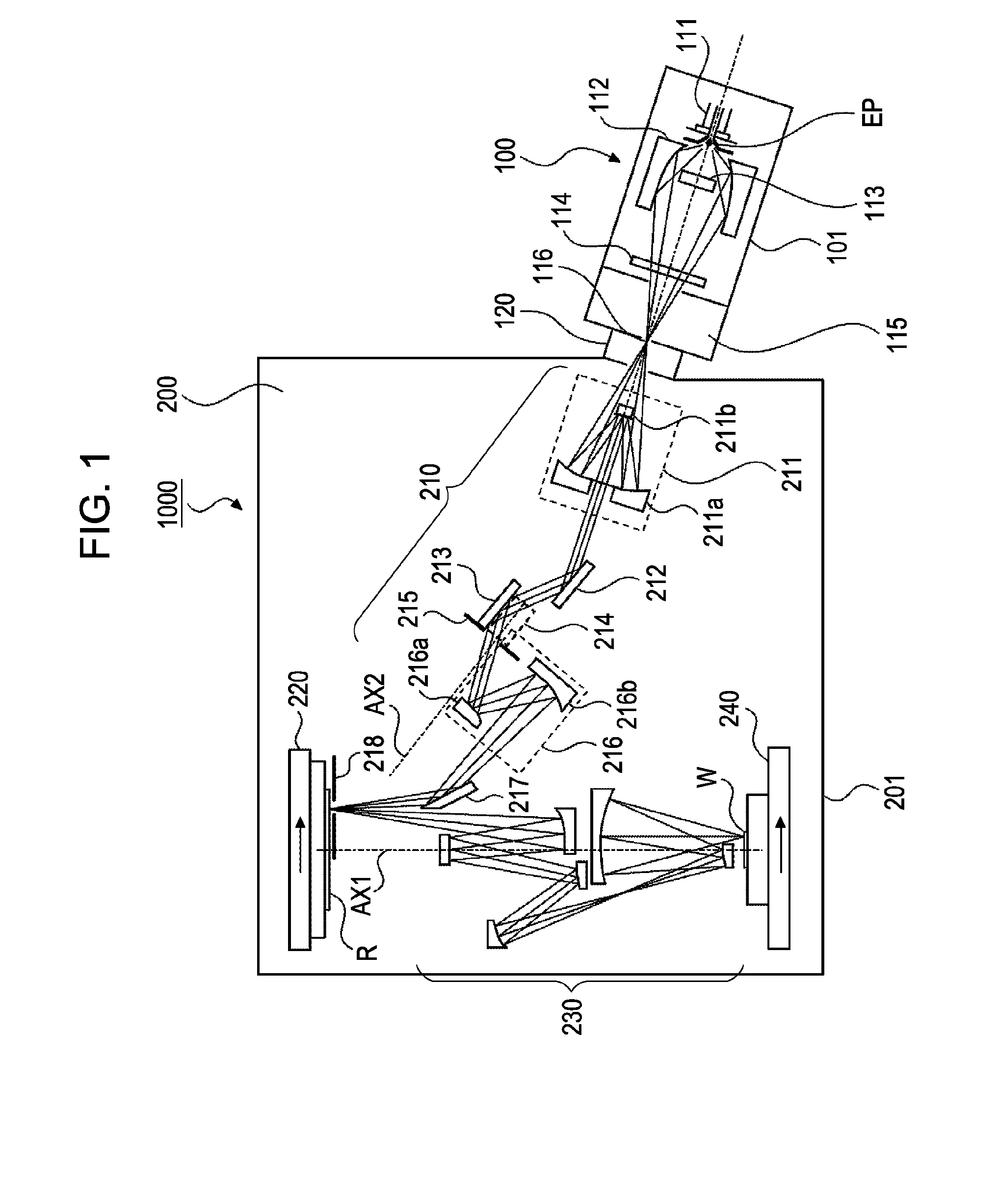
[0050]An exposure apparatus 1000 of a first embodiment will be described referring to FIG. 1, which schematically shows the exposure apparatus 1000.

[0051]The exposure apparatus 1000 is an EUV exposure apparatus in which a circuit pattern formed on a mask R is transferred to a wafer W by exposure, such as step-and-scan exposure, using EUV light (light having a wavelength of 13.5 nm, for example) as exposure light.

[0052]The exposure apparatus 1000 includes a light source unit 100 and a main body 200. The components of the light source unit 100 and the main body 200 are housed in vacuum containers 101 and 201, respectively. The vacuum containers 101 and 201 are connected through a connector 120. The interiors of the vacuum containers 101 and 201 and the connector 120 are kept in a vacuum state during exposure so as to prevent attenuation of the EUV light.

[0053]First, components of the light source unit 100 will be described. The light source unit 100 includes a discharging header 111, ...

second embodiment

[0106]An exposure apparatus according to a second embodiment will now be described. The second embodiment differs from the first embodiment in the configuration of the reflective integrator and the shape of the opening in the aperture stop. Hence, detailed description of other components included in the exposure apparatus are omitted.

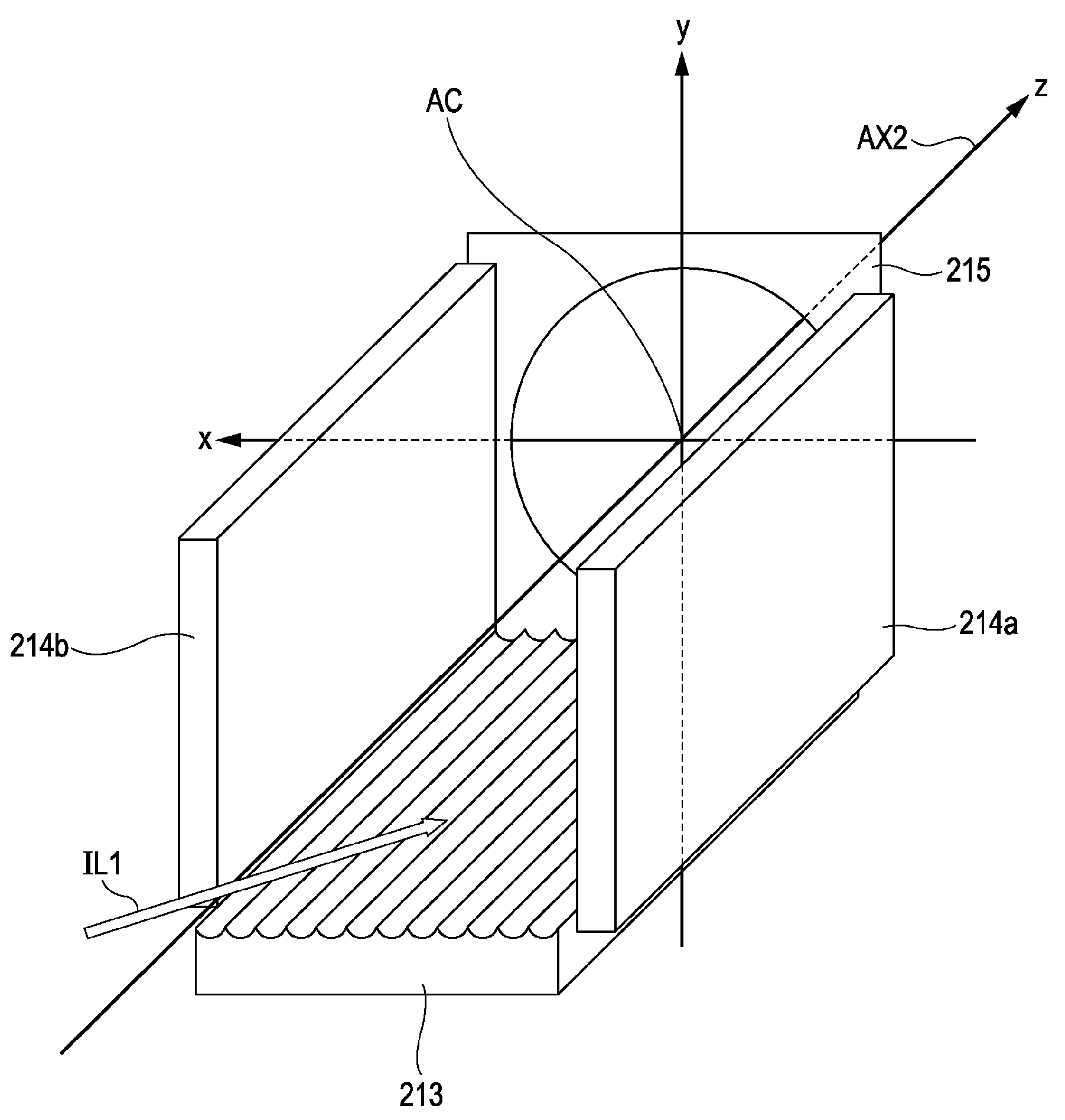
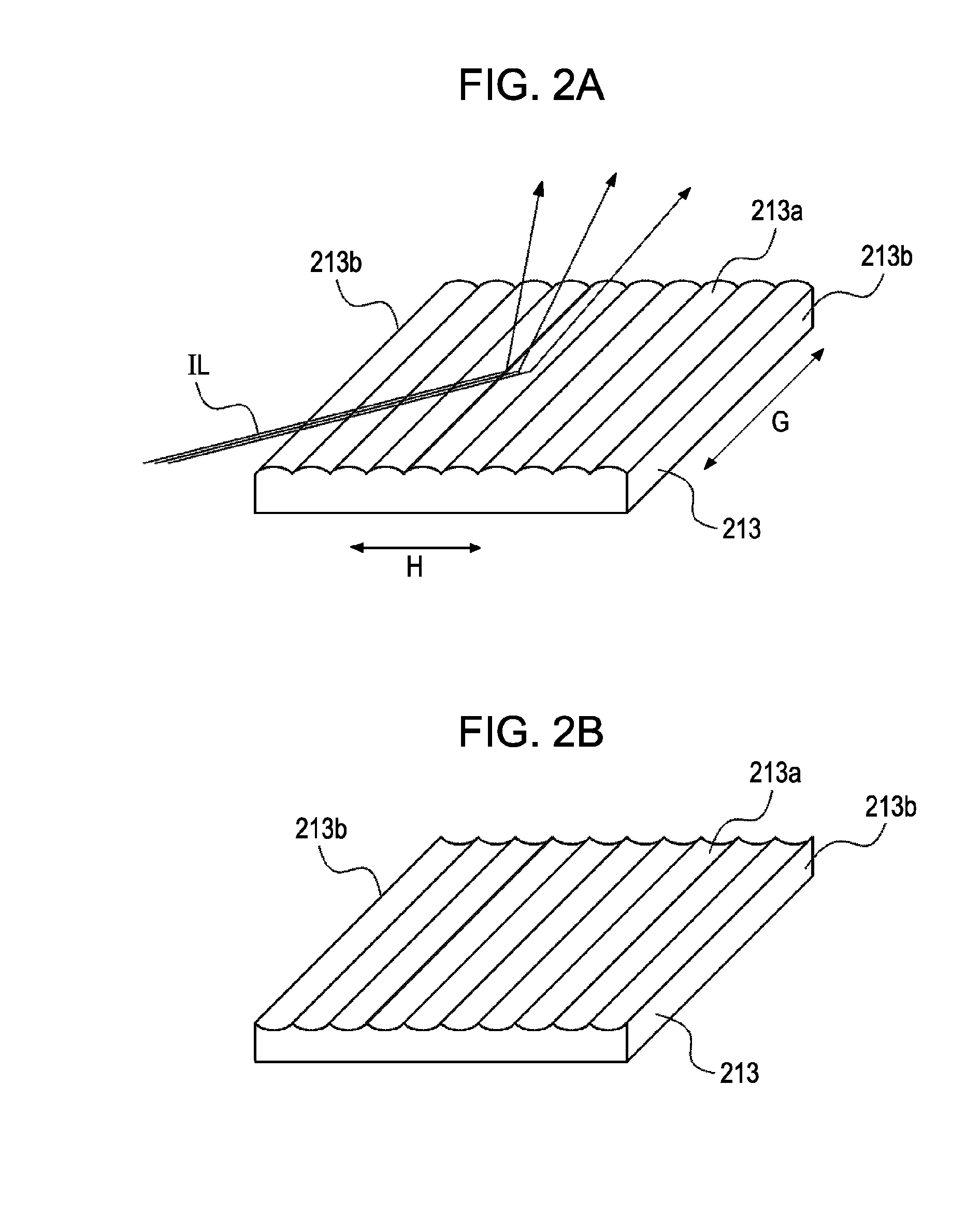
[0107]While the first embodiment concerns a configuration in which the reflective integrator is constituted by a single member having a plurality of cylindrical reflection surfaces, the second embodiment concerns a configuration in which the reflective integrator is constituted by a plurality of integrator segments each having a plurality of cylindrical reflection surfaces. Also with such a reflective integrator, distortion in the distribution shape of effective light sources can be suppressed by disposing an aperture stop on the output side of the reflective integrator. Further, by providing supplementary mirrors on opposite sides of the reflective int...


PUM


Abstract

An illumination optical system includes a first optical unit that collects light emitted from a light source; a reflective integrator that has a plurality of cylindrical reflection surfaces, whose generating lines are oriented in a uniform direction, and forms a plurality of linear light sources by using the light emitted from the first optical unit; a pair of flat mirrors that are disposed parallel to the generating lines so as to face each other with the plurality of linear light sources residing therebetween; an aperture stop that is disposed perpendicular to the generating lines and has an opening for allowing the light emitted from the plurality of linear light sources to pass therethrough; and a second optical unit that integrates beams of the light emitted from the plurality of linear light sources that have passed through the opening one on top of another in an illumination target plane.

Description

BACKGROUND OF THE INVENTION[0001]1. Field of the Invention[0002]The present invention relates to illumination optical systems. An illumination optical system of the present invention is suitable for illumination optical systems such as those included in exposure apparatuses using exposure light of extreme ultraviolet (EUV) having a wavelength of 10 nm to 15 nm.[0003]2. Description of the Related Art[0004]From the viewpoint of improving the resolution, the wavelength of exposure light used in semiconductor exposure apparatuses has been becoming shorter over time. Examples of next-generation exposure apparatuses using a light source having a shorter wavelength include EUV exposure apparatuses, which uses light of the extreme ultraviolet region (EUV light) whose wavelength ranges from 10 nm to 15 nm.[0005]Light of the extreme ultraviolet region is largely absorbed by substances, and is therefore not practical for use with dioptric systems constituted mainly by lenses. Instead, catoptri...

Claims


Application Information

Patent Timeline
Patent Type & Authority Patents(United States)
IPC IPC(8): G03B27/54G03B27/42
CPCG03B27/42G03F7/70075
Inventor KAJIYAMA, KAZUHIKOTSUJI, TOSHIHIKO
Owner CANON KK
Why Eureka
Try Eureka