Braking force control method and device for strip-shaped material feeding device

a technology of strip-shaped material and control method, which is applied in the direction of thin material processing, filament handling, transportation and packaging, etc., can solve the problems of inability to accurately control, reduced work efficiency, and burden on operators

Inactive Publication Date: 2009-06-02
KOMORI CORP
View PDF16 Cites 12 Cited by
  • Summary
  • Abstract
  • Description
  • Claims
  • Application Information

AI Technical Summary

Benefits of technology

[0012]The present invention has been accomplished in light of the above-described problems with the earlier technologies. The present invention provides a braking force control method and device for a strip-shaped material feeding device, which can ensure high accuracy braking force control satisfactorily during long-term use, without imposing a burden on the operator or increasing costs, by effectively switching between braking means such as an air brake and driving means such as an accelerating motor.
[0033]According to the present invention with the above-described features, the frequency of operation of the brake means such as an air brake can be kept to a minimum, management of brake pads, etc. can be facilitated, high accuracy control of a braking force can be ensured satisfactorily during long-term use, and a burden on the operator can be lessened. Furthermore, the capacity of the drive means such as an accelerating motor may be relatively low, because the brake means such as an air brake is used as an aid. Moreover, the drive means may be an existing accelerating motor or the like. Thus, large increases in the costs are avoided.

Problems solved by technology

As a result, variations occur in the control output-torque characteristics (see FIG. 4(b)) of the air brake 104, thus making accurate control impossible.
This has posed the problems that an operator is burdened and the efficiency of work is decreased.
With the braking device of patent document 2 as well, drawbacks similar to those of patent document 1 occur when the braking force of the air brake is used as the main braking force.
As a result, variations occur in the control output-torque characteristics (see FIG. 4(c)) of the air brake, thus making accurate control impossible.
This has posed the problems of burdening the operator and decreasing the work efficiency.
In this case, a motor with a very high capacity is required, presenting the unexpected problem of poor economy.

Method used


Image

  • Braking force control method and device for strip-shaped material feeding device
  • Braking force control method and device for strip-shaped material feeding device
  • Braking force control method and device for strip-shaped material feeding device

Examples


embodiment 1

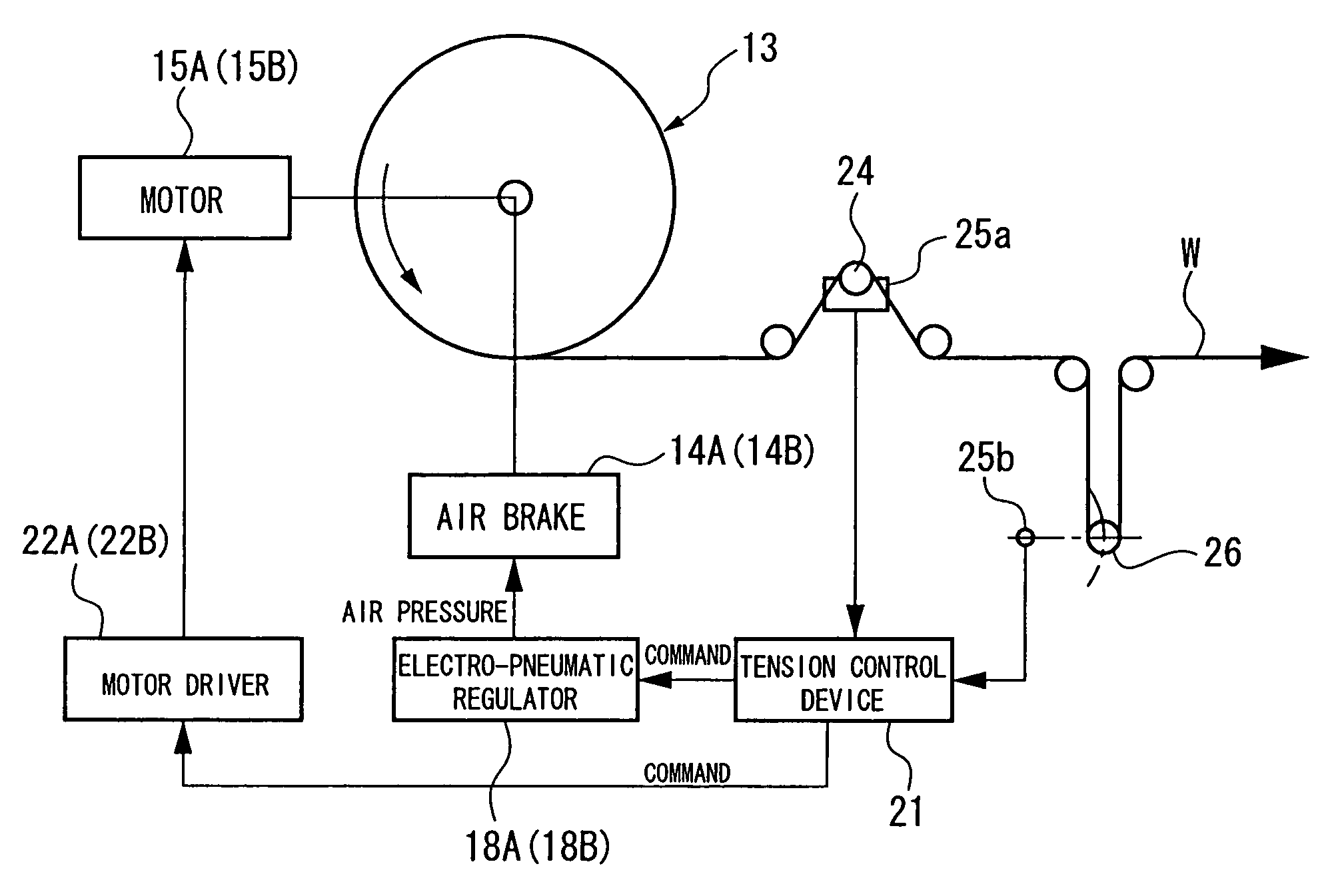
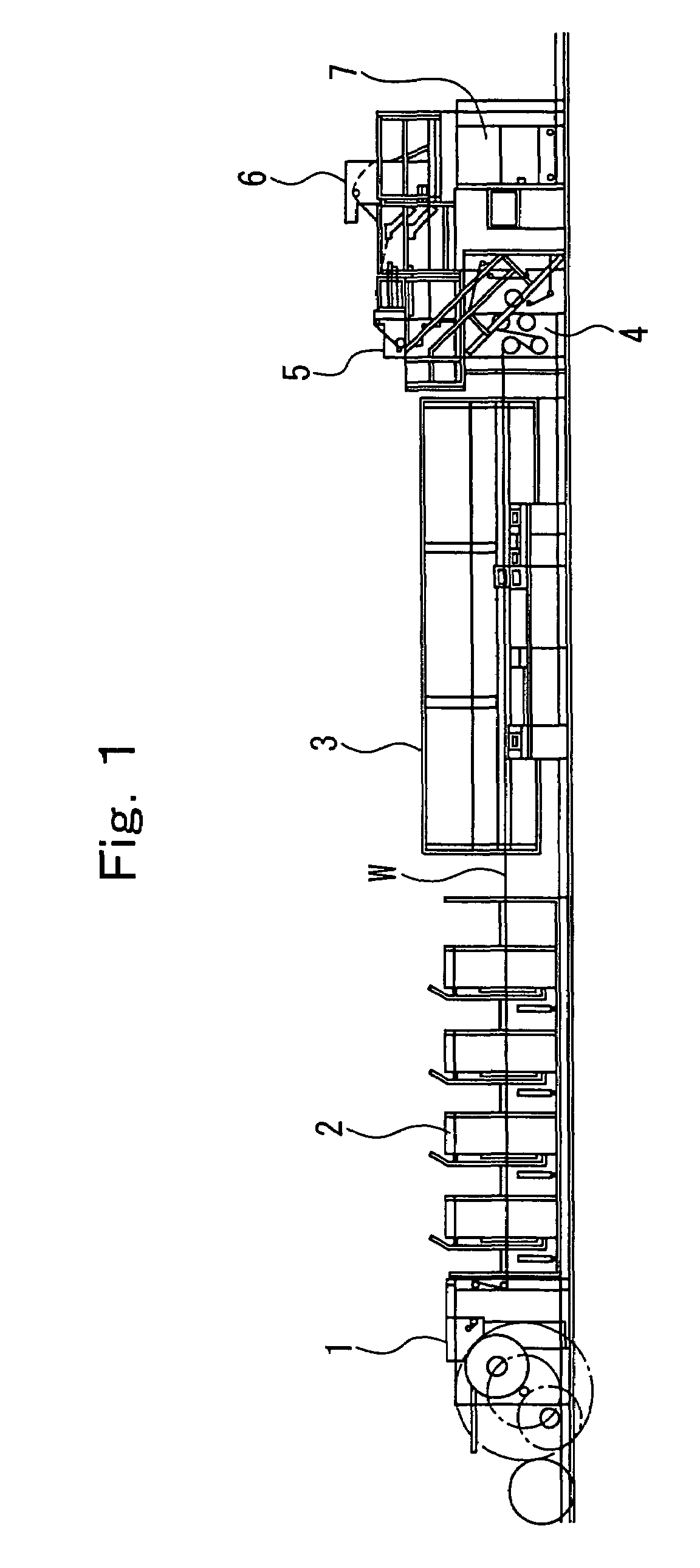
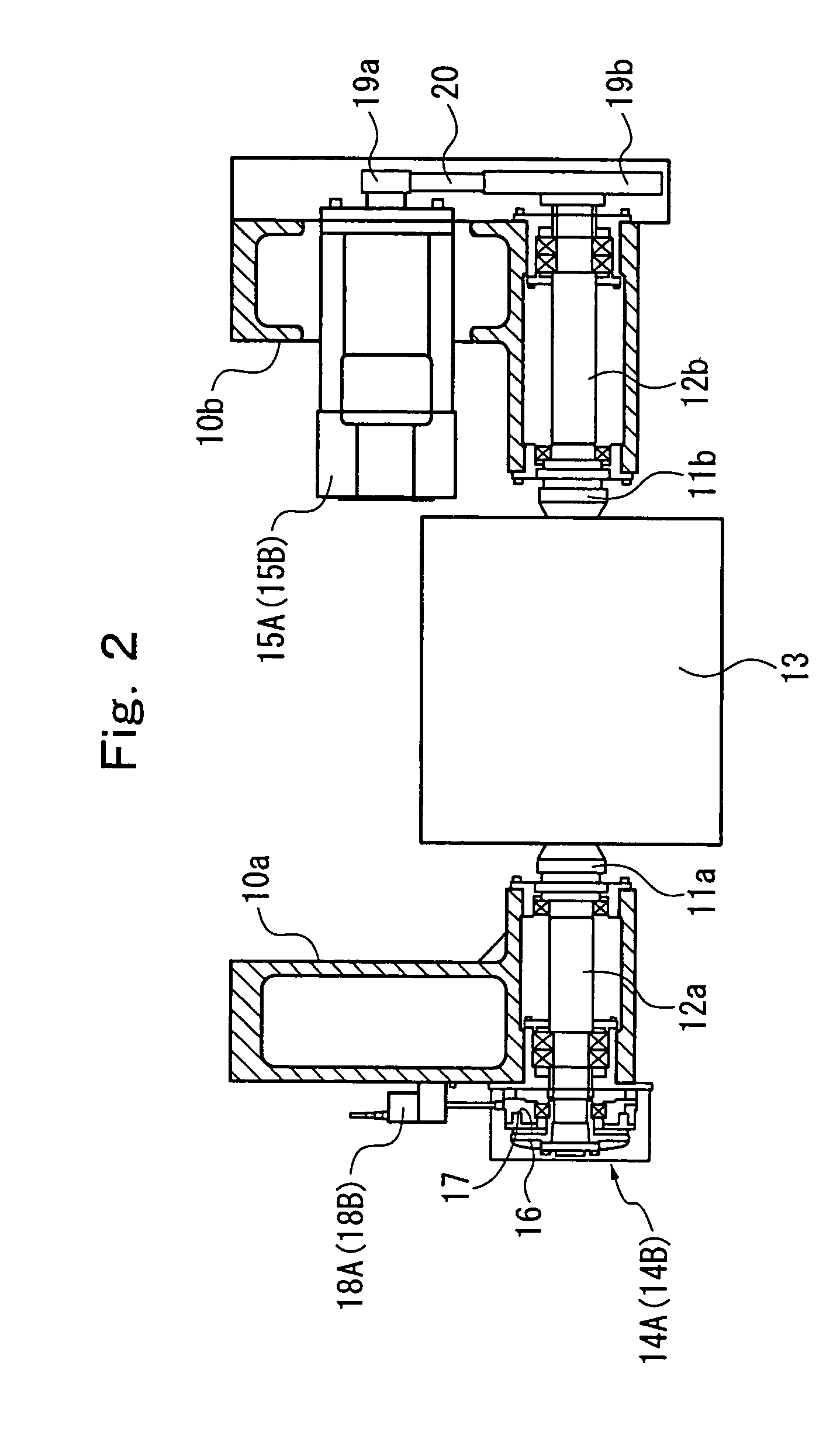
[0059]FIG. 1 is a schematic view of an offset rotary press showing Embodiment 1 of the present invention. FIG. 2 is a sectional view of essential parts of a feeding device. FIG. 3 is a schematic constitutional drawing of a braking force control device. FIGS. 4(a) to 4(c) are comparative explanation drawings of the control output-torque characteristics of the present invention versus earlier technologies. FIG. 5 is a block diagram of a tension control device. FIG. 6 is a detail drawing of essential parts of FIG. 5. FIG. 7 is a block diagram of a control device of the printing press. FIGS. 8 to 13 are action flow charts for the tension control device. FIG. 14 is an action flow chart for the control device of the printing press. FIG. 15 is an action flow chart for a remaining paper length meter.

[0060]In an offset rotary press, as shown in FIG. 1, an unwound strip of paper (web) W, as a strip-shaped material, is continuously supplied from a feeding device 1 as a strip-shaped material (c...

embodiment 2

[0126]FIGS. 16 to 21 are action flow charts for a tension control device showing Embodiment 2 of the present invention.

[0127]This is an embodiment in a case where the capacity of the accelerating motor 15A or 15B is relatively high, and its regenerative braking force has been found to be equal to or greater than the maximum value (constant value) of a braking force required for tension control at an increased speed or a constant speed. In this case, according to the present embodiment, a decision action for control switching between motor regenerative brake torque control (motor regenerative brake torque control +air brake torque control) is not performed, but regenerative brake torque control by the accelerating motor 15A or 15B is directly performed.

[0128]Thus, the action flow charts of FIGS. 16 to 21 are different from the action flow charts of FIGS. 8 to 13 in Embodiment 1 in terms of the actions of Steps Pb57 to Pb79. The actions of Steps Pb1 to Pb56 are the same as the actions...


PUM


Abstract

In a feeding device comprising turret arms having spindle shafts for supporting a web roll, an air brake for applying a braking force in a rotating direction to the spindle shafts, and an accelerating motor for applying a drive force in the rotating direction to the spindle shafts and a braking force in the rotating direction to the spindle shafts, a braking force control device has a tension control device which exercises control such that if a braking force required for the spindle shafts is lower than a constant value, only the braking force from the accelerating motor is supplied to the spindle shafts, and that if the braking force required for the spindle shafts is higher than the constant value, the braking force from the accelerating motor is supplied to the spindle shafts, and the braking force of the air brake is supplied to the spindle shafts.

Description

CROSS REFERENCE TO RELATED APPLICATION[0001]The entire disclosure of Japanese Patent Application No. 2004-136128 filed on Apr. 30, 2004, including specification, claims, drawings and summary, is incorporated herein by reference in its entirety.BACKGROUND OF THE INVENTION[0002]1. Field of the Invention[0003]This invention relates to a braking force control method and device for a strip-shaped material feeding device, which are preferred when applied to a feeding device or the like of a rotary printing press.[0004]2. Description of the Related Art[0005]Examples of a braking device in a feeding device of an offset rotary press include those as shown in FIGS. 22 and 23 (see Japanese Patent Application Laid-Open No. 1995-61661; hereinafter referred to as patent document 1).[0006]In the printing press, a web roll 103 is rotatably supported between a pair of turret arms 100a and 100b via a taper cone 101 and a mechanical chuck 102. According to the braking device, the web roll 103 is brake...

Claims


Application Information

Patent Timeline
Patent Type & Authority Patents(United States)
IPC IPC(8): B65H23/06B65H23/182
CPCB65H23/06
Inventor SHIRAISHI, YOSHIHIDEEBIHARA, HIROMITSU
Owner KOMORI CORP
Why Eureka
Try Eureka