Horizontal multi-blade wind turbine

a horizontal and multi-blade technology, applied in the direction of wind motors with perpendicular air flow, motors, climate sustainability, etc., can solve the problems of unidirectional erection, large high-speed turbines, etc., to maximize fluid engagement and power generation, the effect of maximizing fluid engagemen

Active Publication Date: 2009-06-02
EMSHEY GARRY
View PDF22 Cites 23 Cited by
  • Summary
  • Abstract
  • Description
  • Claims
  • Application Information

AI Technical Summary

Benefits of technology

[0008]Preferably each of the blades is rotated about 120 degrees about the blade axis to maximize fluid engagement and power generation.
[0009]In a further broad aspect a blade suitable for use in the blade system as described comprises: a first end for connection to a rotor of a fluid turbine; and a second free end having an arcuate face so as to maximize fluid engagement.

Problems solved by technology

Such high-speed turbines are generally very large and generally comprise a nacelle mounted for use atop single towers of significant height and diameter.
Such turbines may be unidirectional and erected to take advantage of the usual flow of winds through the location in which they are positioned.

Method used


Image

  • Horizontal multi-blade wind turbine
  • Horizontal multi-blade wind turbine
  • Horizontal multi-blade wind turbine

Examples


Embodiment Construction

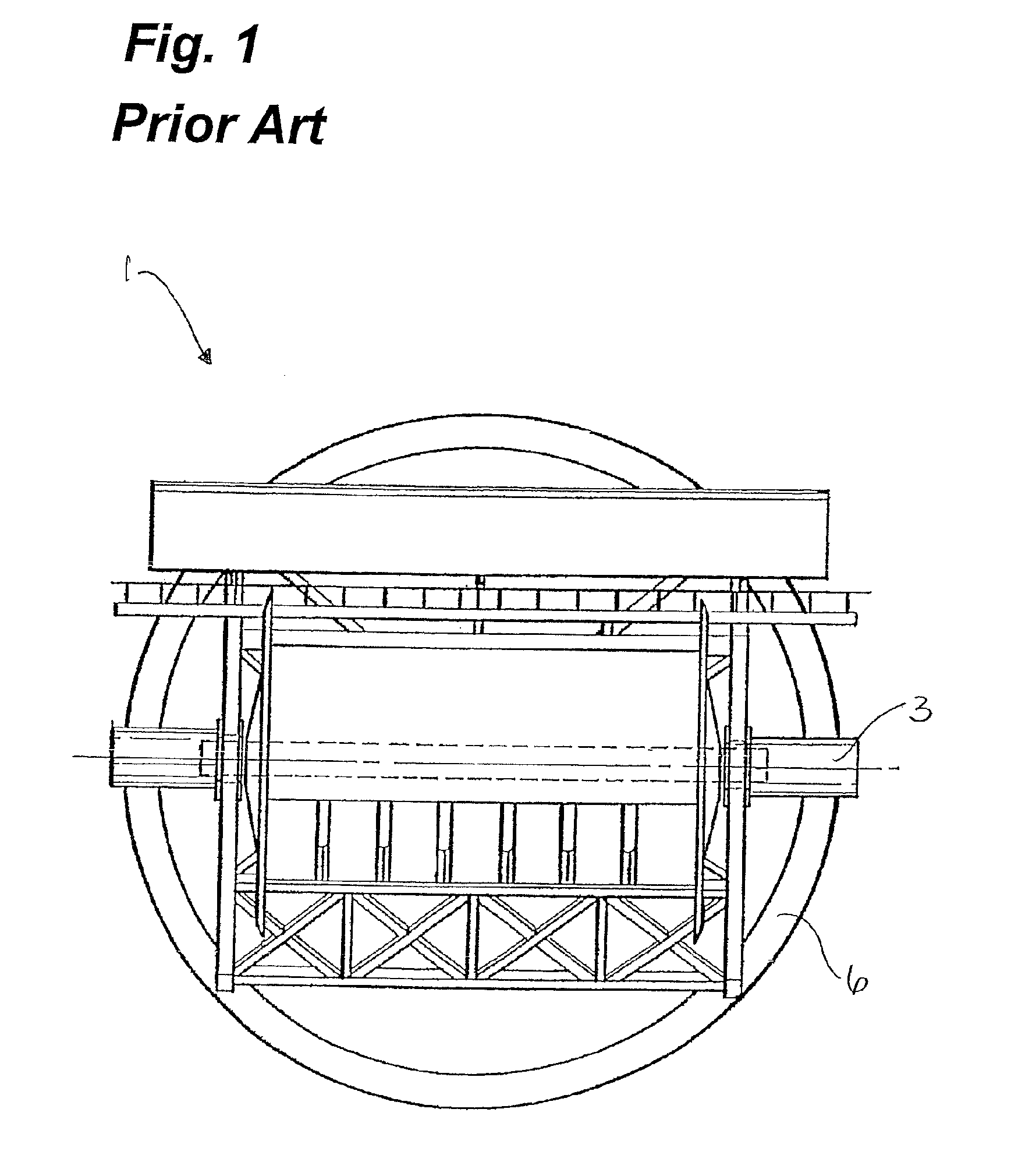
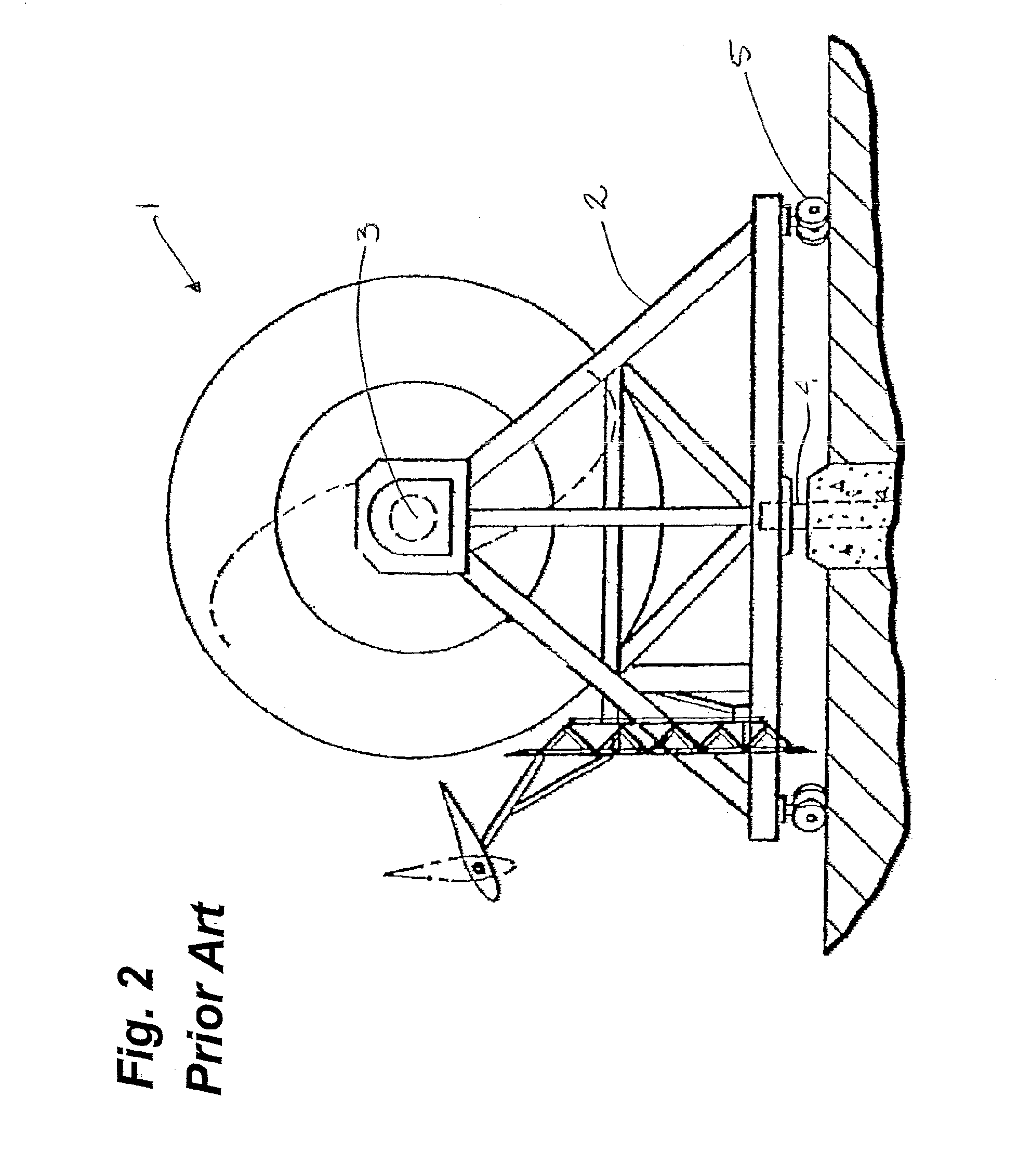
[0027]As shown in FIGS. 1 and 2, a prior art wind turbine 1 such as described in U.S. Pat. No. 4,838,757 to Benesh the entirety of which is incorporated herein by reference. A support structure 2 for a horizontal rotor 3 is provided which pivots about a central vertical shaft 4. The horizontal rotor 3 is supported by the support structure 2. The support structure 2 is further supported on wheels 5, which travel in a circular track 6 to permit the wind generator 1 to rotate in yaw about the vertical central shaft 4.

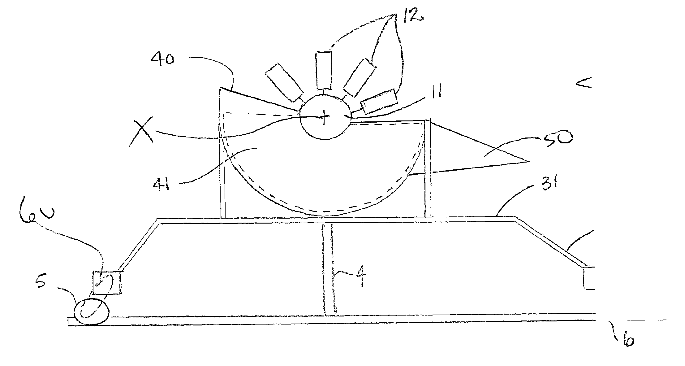
[0028]Having reference to FIGS. 3a and 3b, a fluid turbine 10 according to an embodiment of the present invention is shown. The turbine 10 comprises a horizontal shaft or rotor 11 having a blade system comprising a plurality of blades 12 mounted in rows 13 along a length and extending radially along a blade axis A and spaced about a circumference of the rotor 11. As shown in FIG. 6b, in one embodiment, the plurality of blades 12 in each successive row 13 may be positioned ...


PUM


Abstract

A blade system, has rows of blades extending radially outward along the length and around the circumference of a rotor of a low-profile ground-mounted wind turbine which is particularly suited for use in remote locations. The wind-engaging end of each blade is arc-shaped and is turned about 120 degrees to maximize efficiency. Preferably, two rotors having the unique blade system are connected to a single, centrally located generator, and the entire unit is mounted on a frame which is rotatable on wheels about a central shaft. Further, a circular track is provided in for engaging the wheels for ease of rotation of the unit either under the direction of a PLC or in yaw.

Description

FIELD OF THE INVENTION[0001]Embodiments of the invention are directed towards wind turbines for generating energy and more particularly to a horizontal axis wind turbine having a plurality of blades along the horizontal axis and to a blade suitable for said wind turbine.BACKGROUND OF THE INVENTION[0002]It is well known to use apparatus to generate energy from the wind. Typically, high speed propeller-type turbines have been used due to their high efficiency. Such high-speed turbines are generally very large and generally comprise a nacelle mounted for use atop single towers of significant height and diameter. Such turbines may be unidirectional and erected to take advantage of the usual flow of winds through the location in which they are positioned. Alternatively, the nacelle may be capable of turning in a horizontal plane to adjust the direction of the rotor to face into the oncoming wind.[0003]Many different designs of wind turbines are known. Many wind turbines are oriented vert...

Claims


Application Information

Patent Timeline
Patent Type & Authority Patents(United States)
IPC IPC(8): F03D3/04
CPCF03D3/002F03D3/02F05B2240/941Y02E10/74F03D3/0445
Inventor EMSHEY, GARRY
Owner EMSHEY GARRY
Why Eureka
Try Eureka