Ratcheting-type shrinkage compensating device for use in continuous tie-down systems

a compensating device and continuous tie-down technology, applied in the direction of screws, threaded fasteners, mechanical equipment, etc., can solve the problems of little or no tolerance for any misalignment between the rod and the rt-scd, and the inability to provide a means of assistan

Active Publication Date: 2016-07-12
ALLMON JAMES A +3
View PDF12 Cites 4 Cited by
  • Summary
  • Abstract
  • Description
  • Claims
  • Application Information

AI Technical Summary

Benefits of technology

[0022]b. rod gripping segments with the inner gripping surfaces configured with dual threads, with the threads configured with a specialized thread profile designed to maximize the engagement between the rod gripping segments and the rod;
[0023]c. a body element with inside bore diameters that are greater than the outside diameters of the rod gripping segments, so as to provide a gap between the two, allowing the rod gripping segments to expand freely when the rod ratchets through the RT-SCD;
[0030]j. rod gripping segments that have a continuous exterior circumferential groove, and a band that fits into this groove configured to minimize the differential displacement between the rod gripping segments;

Problems solved by technology

One of the deficiencies with the RT-SCD's that are currently available for use with CTS's is that all of these RT-SCD's currently have rod gripping segments that are configured to engage the standard threads associated with commonly available rod.
The problem with this is that these RT-SCD's can have DATSI values that significantly limit the capacity of the CTS per the requirements set forth in AC316, particularly for large diameter rods with reduced thread pitches.
Another problem with the RT-SCD's depicted in the Schuyler and Brown patents, and the Smith patent application, is that due to their configurations, there is little or no tolerance for any misalignment between the rod and RT-SCD.
Another deficiency with the RT-SCD's that are currently available for use with CTS's is that they do not provide a means that can assist in facilitating the disengagement of the rod gripping segments from the rod.
Another deficiency with the RT-SCD's that are currently available for use with CTS's is that the rod gripping segments sometimes do not all ratchet at the same time as the rod travels through the SCD, particularly when there is a misalignment between the rod and SCD.
When this occurs there is the potential that some of the rod gripping segments will not be in bearing contact with the frusto-conical bore of the body element, and could substantially limit the load capacity of the SCD to that provided by the remaining rod gripping segments that have ratcheted, and are in bearing contact with the frusto-conical bore of the body element.
Another deficiency with the RT-SCD's that are currently available for use with CTS's is that the rod gripping segments are typically free to rotate within the body element of the SCD.
This condition can present problems if the SCD needs to be uninstalled, as the only way to remove one of these SCD's is to spin the SCD back up the rod.
If the rod gripping segments get jammed or locked onto the threads of the rod, then the body will only spin around the rod gripping segments, making it very difficult, if not impossible to remove the SCD without cutting the rod.

Method used


Image

  • Ratcheting-type shrinkage compensating device for use in continuous tie-down systems
  • Ratcheting-type shrinkage compensating device for use in continuous tie-down systems
  • Ratcheting-type shrinkage compensating device for use in continuous tie-down systems

Examples


Embodiment Construction

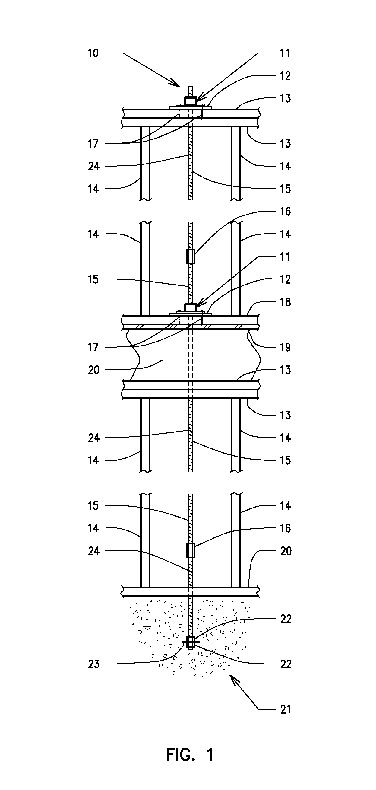
[0064]An embodiment of a CTS 10 that might be used in a multi-story plywood shear wall system to impart tie-down forces is illustrated in FIG. 1. CTS 10 will typically include a plurality of rods 15 interconnected with couplers 16, with one end of the lower rod 15 secured to a concrete foundation element 21 with an anchor plate 23 and nuts 22. Rod 15 will typically be provided with rod deformations 24, which will typically consist of a standard thread profile, but can also consist of a custom or specialized thread profile, or unique deformation pattern.

[0065]The CTS 10 is typically located equidistant between studs 14, and extends from foundation 21, through a sill plate 20, top plates 13, rim joist and / or blocking 20, plywood sheathing 19, sill plate 18, and top plates 13. The CTS 10 is secured to various building elements at the various levels of a multi-story plywood shearwall system, including sill plates 18 and / or top plates 13, with an RT-SCD 11 and base plate 12. Each RT-SCD ...


PUM


Abstract

A ratcheting-type rod engaging nut and assembly for releasably engaging a tie-down rod, and including a generally cylindrical body element having an upper cylindrical portion of a first diameter, a lower cylindrical portion of a second diameter less than the first diameter, and a tapered bore coaxial with and interconnecting the upper bore and the lower bore; an assembly of rod gripping segments disposed within the internal bore and surrounding a passageway for receiving a tie-down rod, each segment of the assembly including an outwardly facing surface having a tapered portion for engaging the tapered bore, and an inwardly facing surface for engaging the rod. A cap is disposed at the top of the body element and includes springs for downwardly biasing the segments into engagement with the tapered bore and for causing the facing surfaces of the segments to engage an outer surface of the rod.

Description

FIELD OF INVENTION[0001]The present invention relates generally to building construction components, and in particular, to an improved ratcheting type shrinkage compensating device used in continuous tie-down systems.BACKGROUND[0002]A Shrinkage Compensating Device (SCD) is generally included as a sub-component of a Continuous Tie-down System (CTS). CTS's are a critical element of both single and multi-story plywood shearwall systems, such as those used in multi-unit timber framed residential construction, and are designed to resist the overturning forces associated with those types of shearwalls. A CTS is typically located near each end of a shearwall system, and will generally consist of one or more lengths of rod or all-thread rod interconnected with couplers. One end of the CTS is typically anchored to a fixed foundation element and then attached to each level of the plywood shearwall system with a bearing plate and SCD.[0003]The purpose of the SCD is to compensate for any differ...

Claims


Application Information

Patent Timeline
Patent Type & Authority Patents(United States)
IPC IPC(8): E04B1/38E04B1/26F16B37/08F16B35/04E04C5/00E04B1/35
CPCF16B35/04E04B1/26F16B37/0857E04B2001/268E04B2001/2688E04B2001/3583
Inventor ALLMON, JAMES A.HILL, NOAH S.PRYOR, JOHN D.SCHUYLER, PETER W.
Owner ALLMON JAMES A
Why Eureka
Try Eureka