

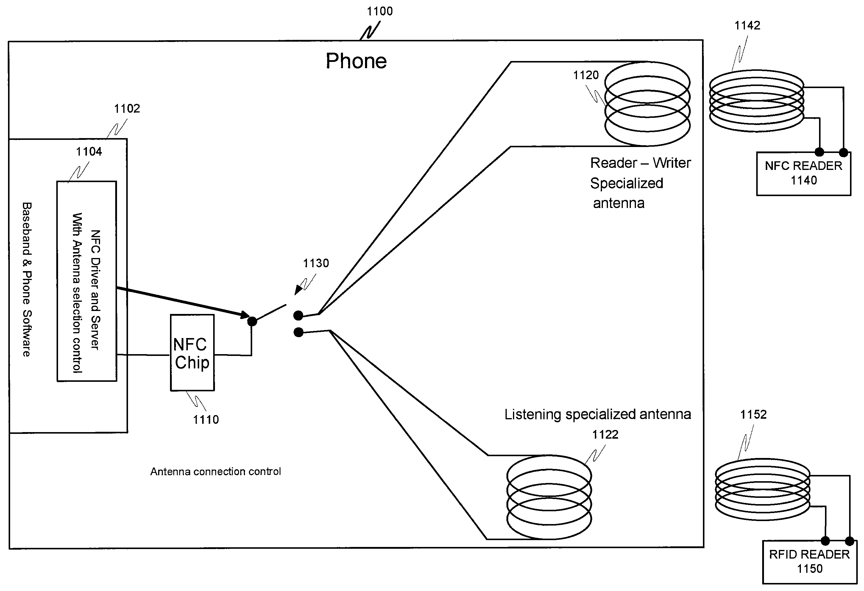
Apparatus and method for controlling diverse short-range antennas of a near field communications circuit
a near field communication and antenna control technology, applied in the field of wireless communication, can solve the problems of reducing the effective communication range of the reader/tag transponder, defeating the primary purpose of establishing the service point, and cellular network may not be suitable for all data applications, so as to achieve the effect of increasing the range of the machine-readable tag
- Summary
- Abstract
- Description
- Claims
- Application Information
AI Technical Summary
Benefits of technology
Problems solved by technology
Method used
Image

Examples
Embodiment Construction
[0039]While the invention has been described in preferred embodiments, various changes can be made therein without departing from the spirit and scope of the invention, as described in the appended claims.
[0040]The present invention may be employed in enhancing or extending the communication ability of a short-range machine-readable tag. While RFID tags will be discussed throughout the specification, the same system may be applied to any short-range machine-readable communication technology employing similar communication characteristics.
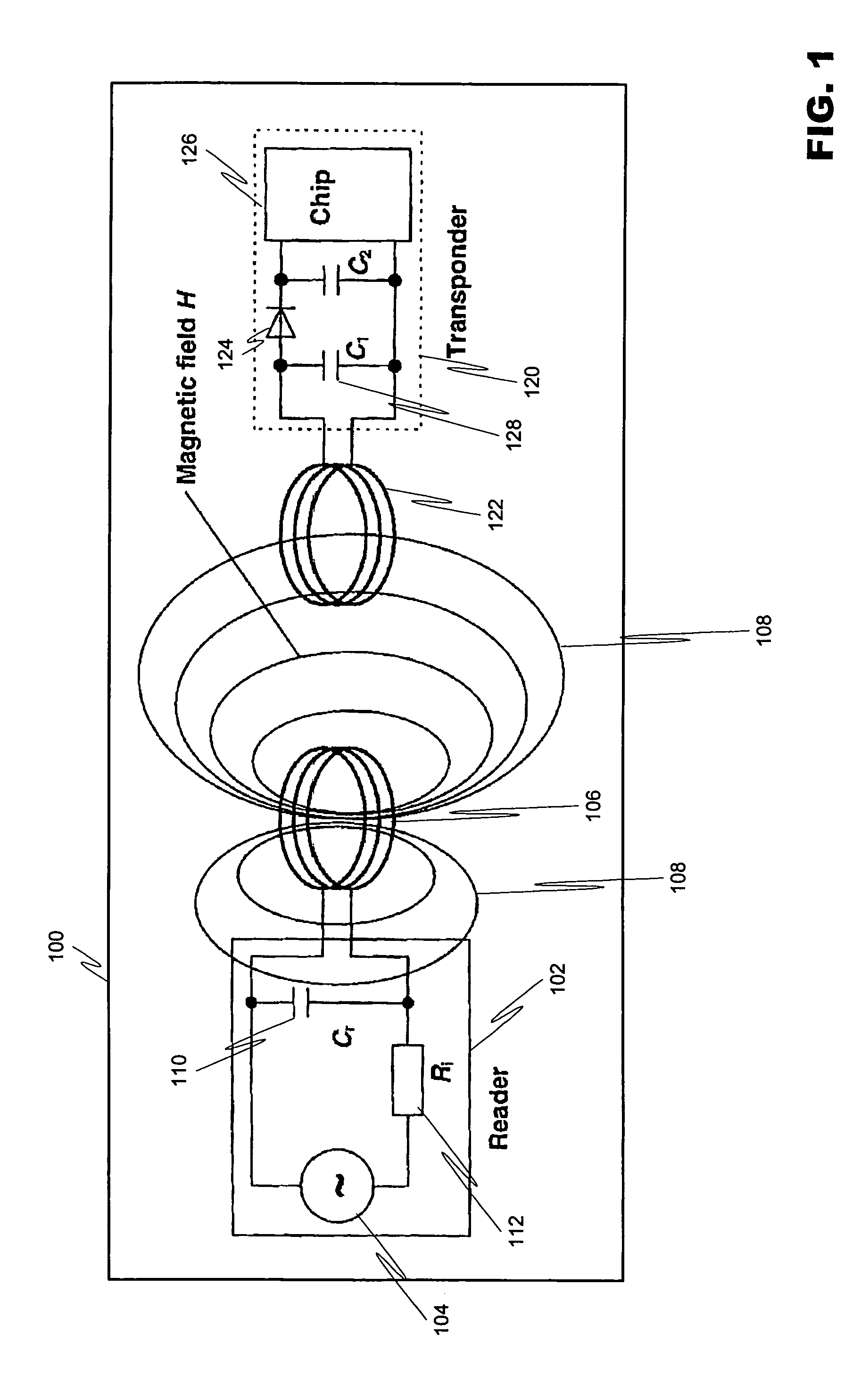
[0041]FIG. 1 depicts a baseline RFID reader / transponder system 100, which includes the reader 102 (also known as a scanner) and the transponder 120. The reader 102 includes an AC power source 104 connected to the reader's antenna coil 106, which generates a strong, high frequency electromagnetic field in the area around the reader's antenna coil 106. The strength of the field depends on the power source and the size and number of turns in the coil. ...
PUM
 Abstract
Description
Claims
Application Information