Adjustable fence assembly for chop saw

a technology of fence assembly and chop saw, which is applied in the field of fence assembly for cutoff machines, can solve the problems of time-consuming and labor-intensive adjustment of fence assembly length, and achieve the effect of convenient us

Inactive Publication Date: 2009-06-09
REXON IND CORP LTD
View PDF30 Cites 8 Cited by
  • Summary
  • Abstract
  • Description
  • Claims
  • Application Information

AI Technical Summary

Benefits of technology

[0006]The present invention has been accomplished to provide a fence assembly for a cut-off machine, which eliminates the drawbacks of the aforesaid conventional design.
[0008]When the press member presses the stop block, the fastener provides a clamping force that holds the stop block, the locating block, the fence plate and the fence base together. The stop block is stopped from moving upwardly, and the bottom panel of the fence plate is firmly sandwiched between the locating block and the fence base, prohibiting sliding movement of the fence plate along the fence base. When the press member is operated so as not to press the stop block and thus make the stop block moved upwardly, slightly, the clamping force of the fastener is removed or reduced so as to allow sliding movement of the fence plate relative to the fence base. Further, releasing the press member will fasten the fence plate again by returning the press member and the stop block to their former positions. This design is convenient to use.

Problems solved by technology

According to this design, it is time-consuming to adjust the length of the fence assembly 60.

Method used


Image

  • Adjustable fence assembly for chop saw
  • Adjustable fence assembly for chop saw
  • Adjustable fence assembly for chop saw

Examples


Embodiment Construction

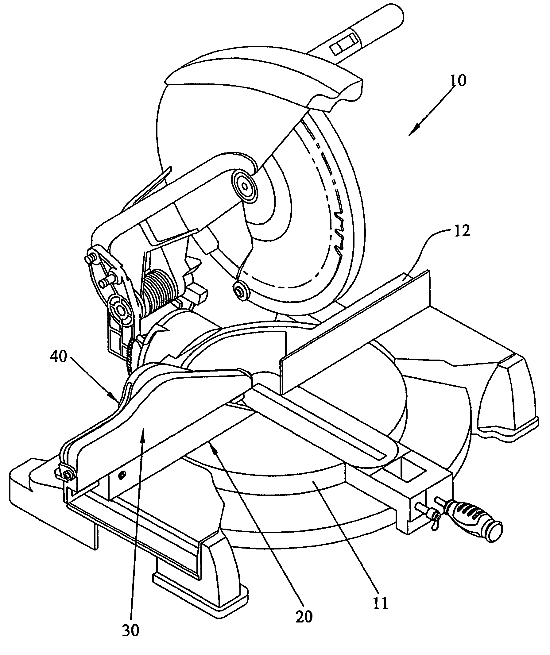
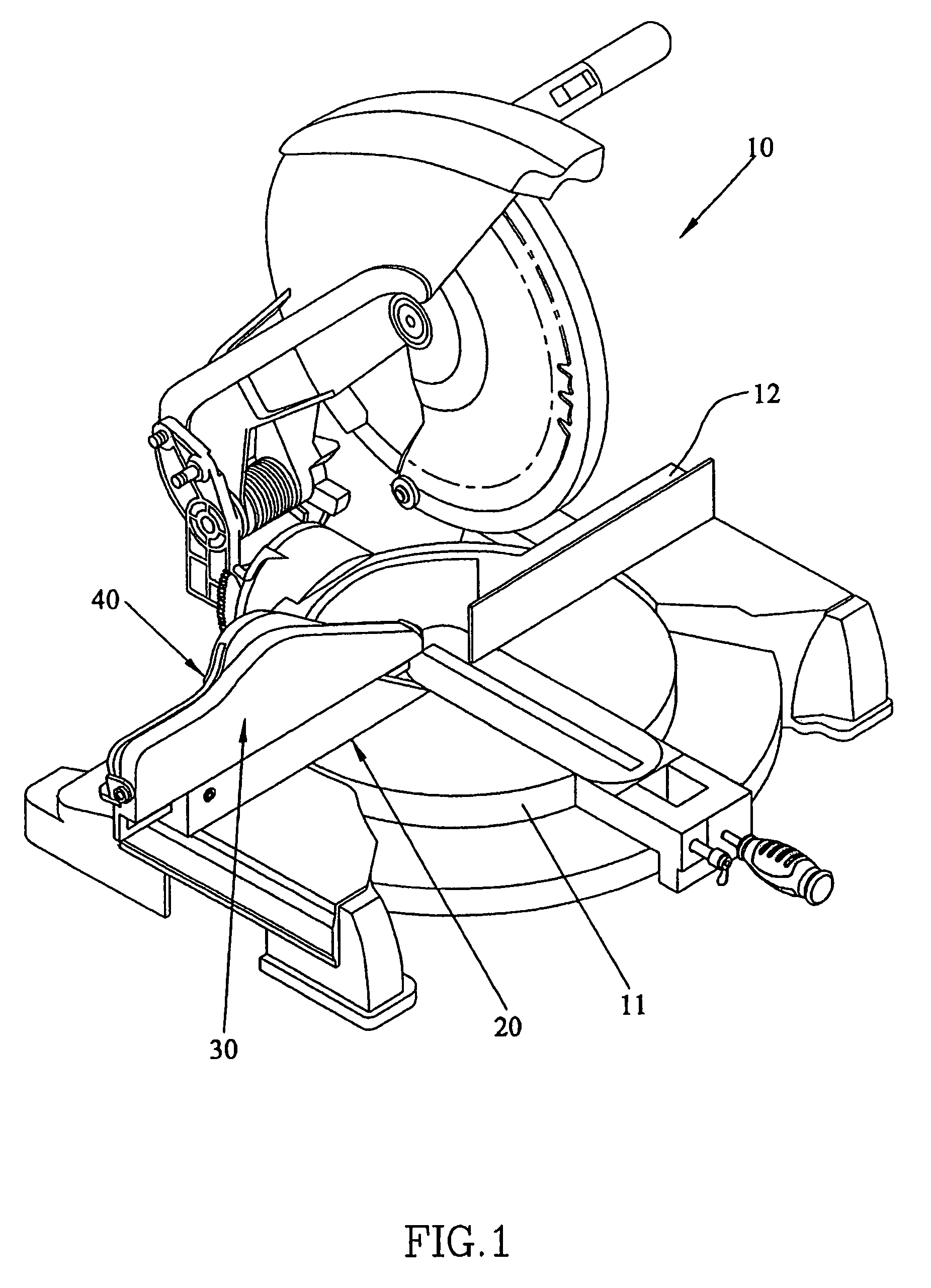
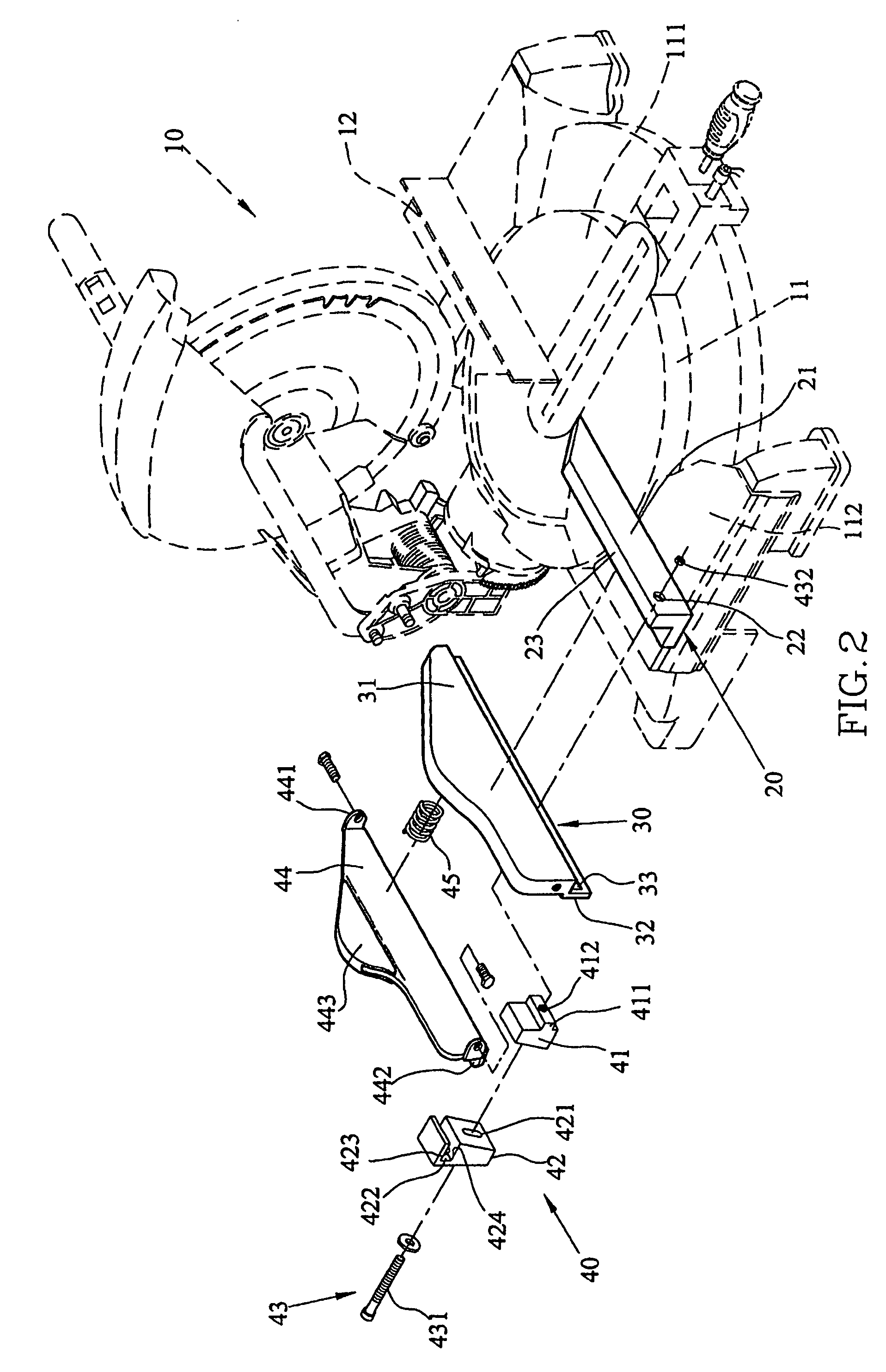
[0017]Referring to FIGS. 1˜4, a fence assembly 12 in accordance with the present invention is shown installed in a cut-off machine 10. According to an embodiment, the cut-off machine 10 includes a worktable 11. The fence assembly 12 is provided on the top side of the worktable 11 for stopping a workpiece put on the worktable 11 in a position to be cut by the cut-off machine 10.

[0018]The fence assembly 12 includes a fence base 20, a fence plate 30 mounted on the fence base 20, and a locking structure 40. The aforesaid worktable 11 may be made in a fixed form or rotatable form. The fence assembly 12 is applicable to either a fixed form or rotatable form of the worktable. According to this embodiment, the worktable 11 is a rotatable design including a fixed table 112 and a rotating table 111 rotatably supported on the fixed table 112. The fence base 20 is fixedly mounted on the fixed table 112 and extends over the top side of the rotating table 111, and further having an upright sidewa...


PUM

PropertyMeasurementUnit
lengthaaaaaaaaaa
widthaaaaaaaaaa
external forceaaaaaaaaaa

Abstract

A fence assembly of a cut-off machine includes a fence base fixed above a worktable of the cut-off machine, a fence plate supported on and movable along the fence base, having a downwardly extending bottom panel and a locking structure for controlling whether the fence plate is locked to the fence base. The locking structure includes a fastener defining a separation with a constant length from the fence base, a first block, a second block and a press member. The first block, the second block and the bottom panel are positioned in the constant separation. The bottom panel is disposed between the second block and the fence base. The contact surface between the first block and the second block slopes toward the direction of the separation. The first block is movable substantially perpendicularly to the direction of the separation. The press member selectively presses the first block.

Description

BACKGROUND[0001]1. Field of the Invention[0002]The present invention relates to a cut-off machine and more specifically, to a fence assembly for a cut-off machine.[0003]2. Description of the Related Art[0004]Referring to FIG. 8, a conventional cut-off machine 50 includes a worktable 51, a saw arm 52, a saw blade 53 and a fence assembly 60. The worktable 51 may be made in a fixed form or rotatable form. The worktable 51 shown in FIG. 8 is a rotatable form, including a rotating table 54 and a fixed table 55. The fence assembly 60 is installed on the fixed table 55 and extends over the rotating table 54, and further having a lateral side perpendicular to the top surface of the rotating table 54. The saw arm 52 has one end pivotally or rotatably connected to the rear side of the rotating table 54, and the other end holding the saw blade 53. The workpiece to be cut is placed on the worktable 51 at a suitable location. When lowering the saw arm 52, the saw blade 53 cuts the workpiece. For...

Claims


Application Information

Patent Timeline
Patent Type & Authority Patents(United States)
IPC IPC(8): B26D1/18
CPCB27B27/00Y10T83/5815Y10T83/7593Y10T83/7726Y10T83/7788
Inventor CHEN, JUNG-HUO
Owner REXON IND CORP LTD
Why Eureka
Try Eureka