Garbage bin

a garbage bin and garbage technology, applied in the field of garbage bins, can solve problems such as problems, and achieve the effect of ensuring positioning and ensuring integrity

Inactive Publication Date: 2009-06-09
LIN TSONG YOW
View PDF35 Cites 86 Cited by
  • Summary
  • Abstract
  • Description
  • Claims
  • Application Information

AI Technical Summary

Benefits of technology

[0012]It is an advantage of the garbage-containing device of the present invention to ensure its integrity, since the second ring is pivotally connected to the first ring and, hence, will not be lost.
[0013]It is another advantage of the garbage-containing device of the present invention to ensure the positioning of the bag, since the upper edge of the bag is clamped between the first and second rings.

Problems solved by technology

Some problems have been encountered during the use of the bin 1 and the bag-holding device 2.
This is inconvenient.
Some problems have been encountered during the use of the conventional garbage-containing device 120.

Method used


Image

  • Garbage bin
  • Garbage bin
  • Garbage bin

Examples


Embodiment Construction

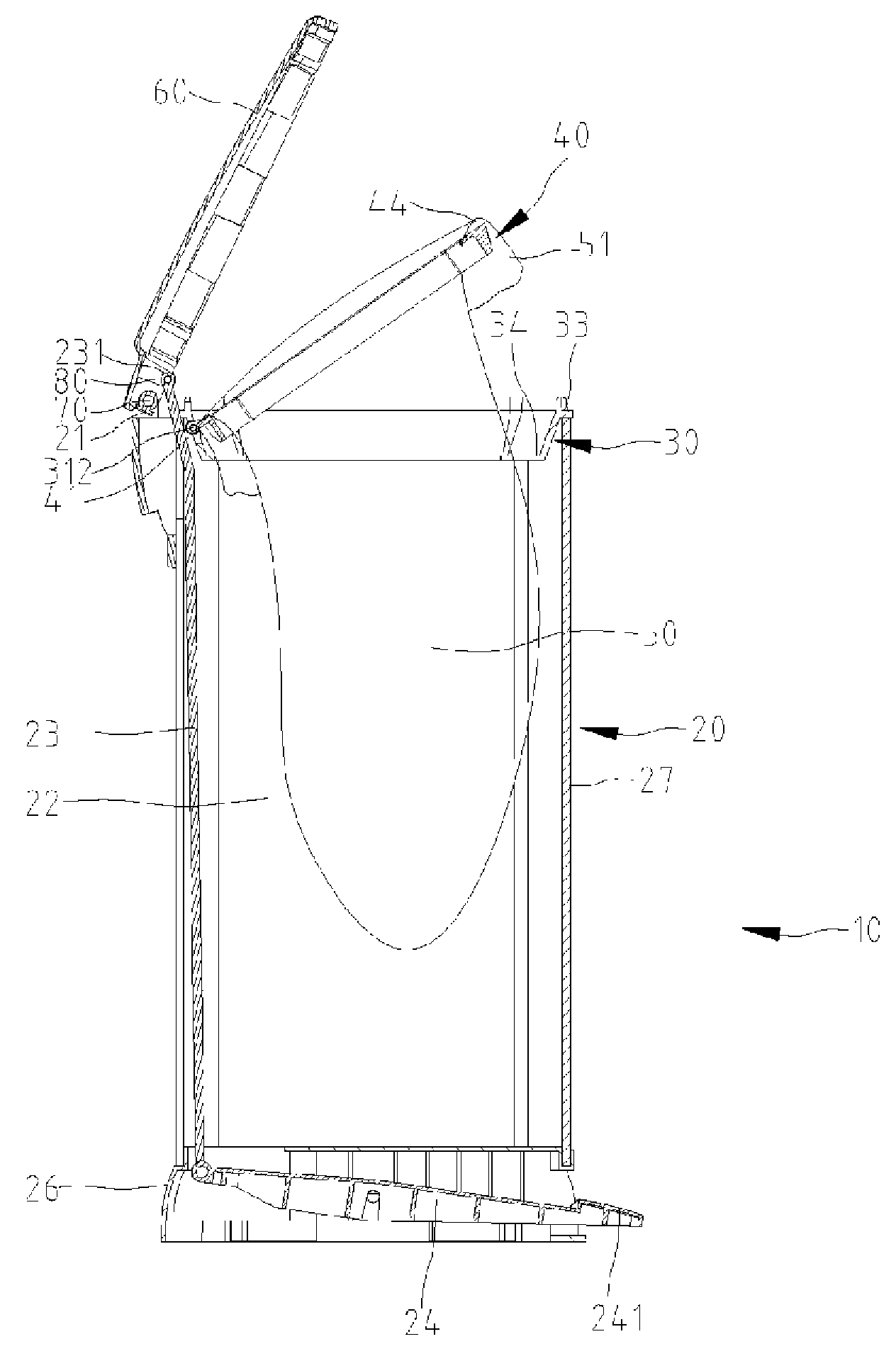
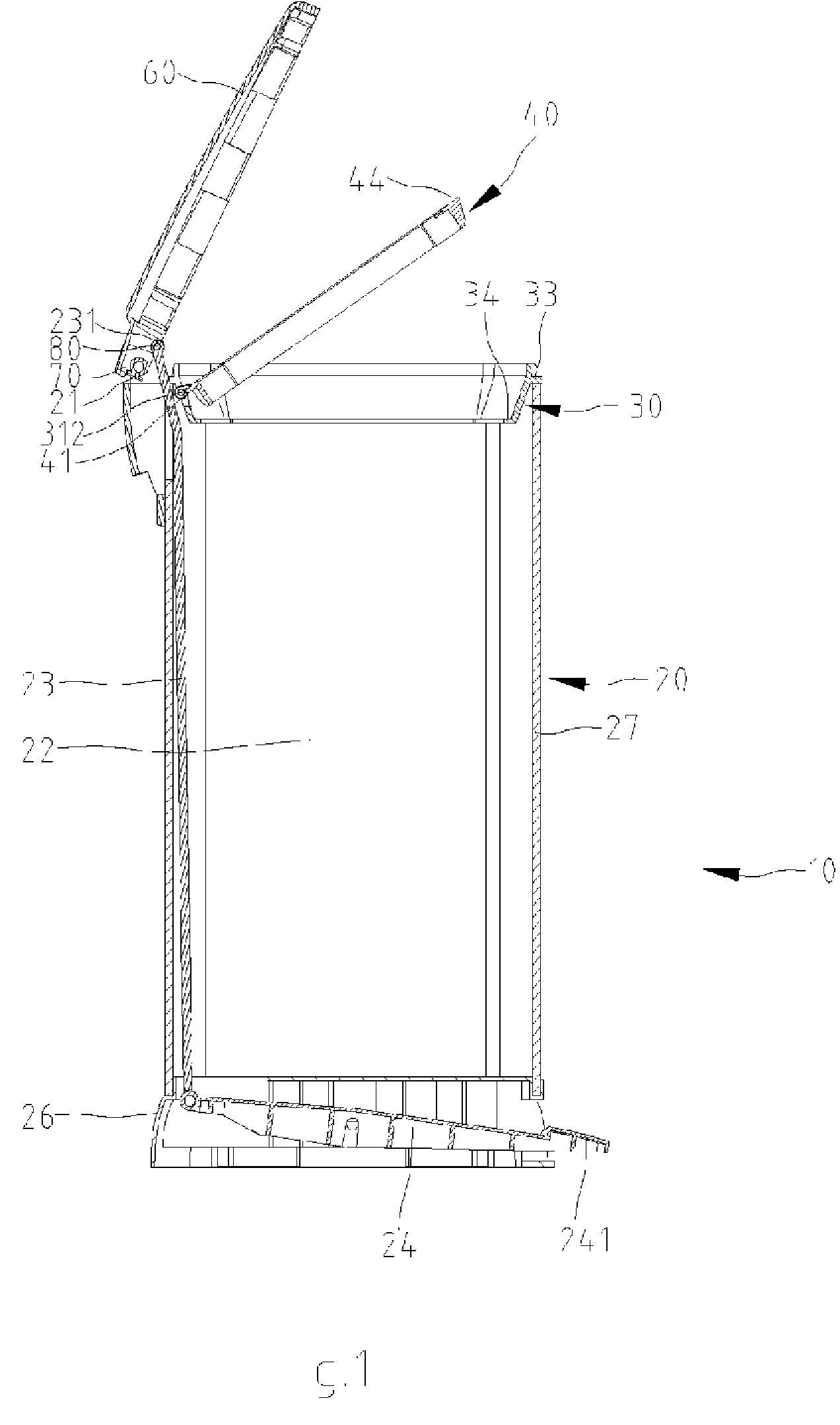
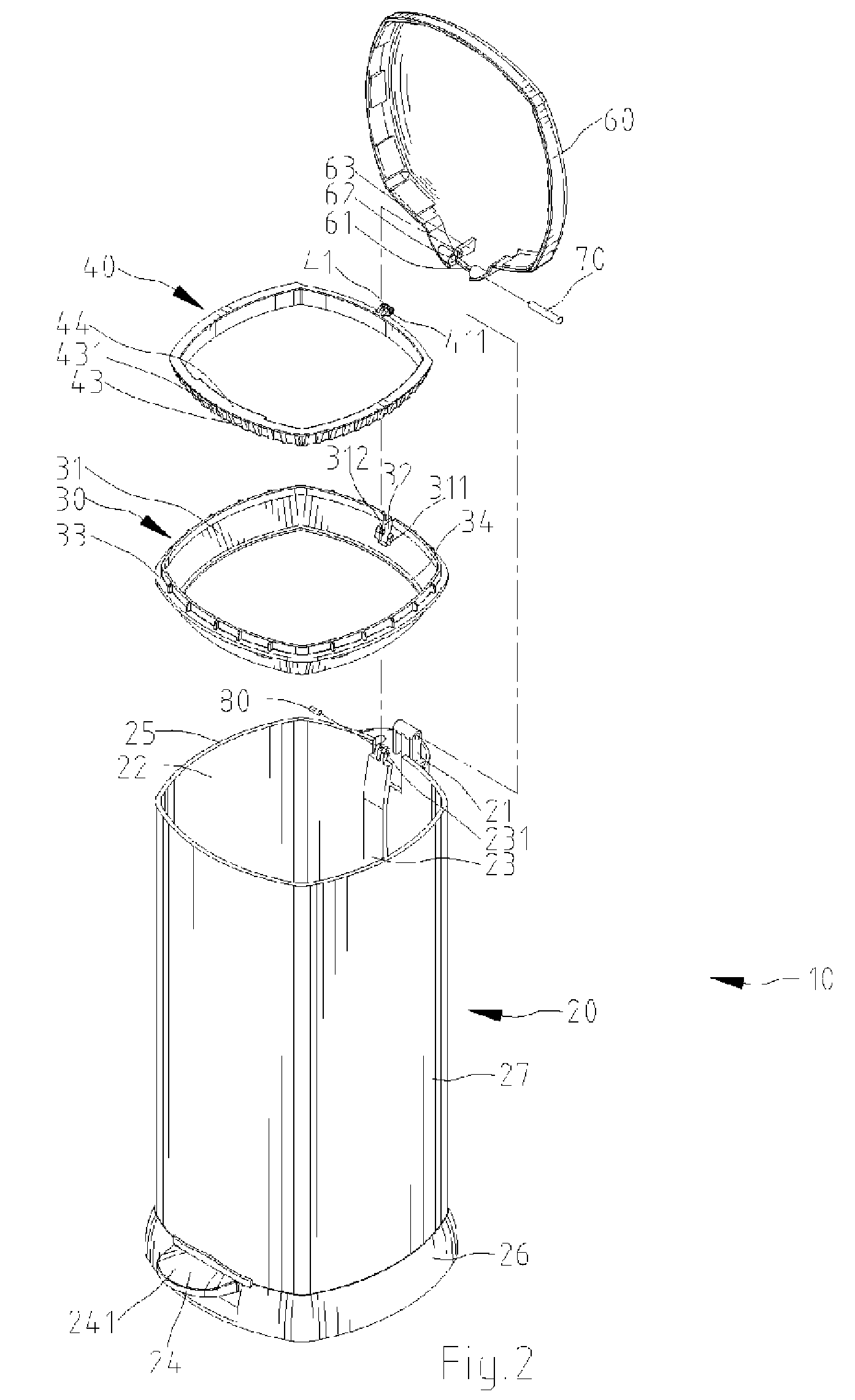
[0025]Referring to FIGS. 1 and 2, there is shown a garbage-containing device 10 according to a first embodiment of the present invention. The garbage-containing device 10 includes a bin 20, a first ring 30, a second ring 40 and a cover 60.

[0026]The bin 20 includes a base 26 and a barrel 27 installed on the base 26. The barrel 27 defines a space 22 and includes an upper edge 25 and a connective portion 21 near the upper edge 25.

[0027]The cover 60 includes two sleeves 62 formed on a lower side and separated by a gap 61 and a lug 63 formed on the lower side.

[0028]The cover 60 is installed on the barrel 27. The connective portion 21 of the barrel 27 is located between the sleeves 62 of the cover 60. A pin 70 is fit in the sleeves 62 of the cover 60 and the connective portion 21 of the barrel 27, thus pivotally installing the cover 60 on the barrel 27.

[0029]A pedal 24 is pivotally installed on the base 26 and, more specifically, between the base 26 and the barrel 27. The pedal 24 include...


PUM

PropertyMeasurementUnit
weightaaaaaaaaaa
depthaaaaaaaaaa
structureaaaaaaaaaa

Abstract

A garbage-containing device includes a bin, a first ring and a second ring. The first ring is installed on the bin. The second ring is pivotally installed on the first ring. An upper edge of a bag can be clamped between the first and second rings.

Description

BACKGROUND OF INVENTION[0001]1. Field of the Invention[0002]The present invention relates to a garbage bin and, more particularly, to a device for holding a garbage bag in a garbage bin.[0003]2. Related Prior Art[0004]Disclosed in Taiwanese Patent M261490 is a bin 1 capable of holding a bag. Referring to FIGS. 1 and 2 of the patent, the bin 1 includes an opening 11 at an upper end and two enhanced portions 15 near the upper end. A bag-holding device 2 is installed on the bin 1. The bag-holding device 2 is made corresponding to the opening 11. The bag-holding device 2 includes two arched frames 21 and 22. Each of the frames 21 and 22 includes two ends each formed with a lug 23. A fastener 3 is driven into one of the lugs 23 of the frame 21, a related one of the lugs 23 of the frame 22 and a related one of the enhanced portions 15. Thus, the frames 21 and 22 are pivotally installed on the bin 1.[0005]Referring to FIGS. 3 and 4 of the patent, the frames 21 and 22 are lifted. An upper e...

Claims


Application Information

Patent Timeline
Patent Type & Authority Patents(United States)
IPC IPC(8): B65D25/14
CPCB65F1/06B65F1/163Y10S220/908
Inventor LIN, TSONG-YOW
Owner LIN TSONG YOW
Why Eureka
Try Eureka