Disk drive with vibration suppression member disposed near head assembly

a technology of vibration suppression and head assembly, which is applied in the direction of electrical apparatus construction details, instruments, and record information storage, etc., can solve the problems of central axis deviation of the head assembly secured to the top cover, affecting the accuracy of read/write operations, etc., and achieves the effect of suppressing surface deformation

Inactive Publication Date: 2009-06-09
WESTERN DIGITAL TECH INC
View PDF9 Cites 3 Cited by
  • Summary
  • Abstract
  • Description
  • Claims
  • Application Information

AI Technical Summary

Benefits of technology

[0009]It is therefore a feature of the present invention to provide a disk drive suppressing surface deformation of the top cover.
[0010]In accordance with an aspect of the present invention, a disk drive includes a base and a top cover portion. The base accommodates a head assembly, a circuit unit, and a recording medium. The top cover portion is supported by the base at a plurality of inner points of support and peripheral edge points of support on a peripheral edge portion near a portion accommodating the head assembly and the circuit unit. The top cover portion covers the accommodating portion of the base. The head assembly is rotatably supported within the base and a rotational axis of the head assembly is secured to the top cover. Further, a vibration suppression member is disposed in a polygon. This polygon has, as vertices, a plurality of inner points of support, and of the peripheral edge points of support, the peripheral edge points of support near the portion accommodating the head assembly and the circuit unit, at a corresponding position in the polygonal portion corresponding to an area near a loop of vibration in a surface of the top cover. The vibration suppression member functions to suppress the vibration of the top cover portion.

Problems solved by technology

Under these circumstances, a problem as described in the following arises at sites where computer apparatus and the like mounted with disk drives are implemented.
The impact can also cause a central axis of the head assembly secured to the top cover to deviate.
Consequently, there arise greater part-to-part variations in the head flying height, affecting accuracy in read / write operations.

Method used


Image

  • Disk drive with vibration suppression member disposed near head assembly
  • Disk drive with vibration suppression member disposed near head assembly
  • Disk drive with vibration suppression member disposed near head assembly

Examples


Embodiment Construction

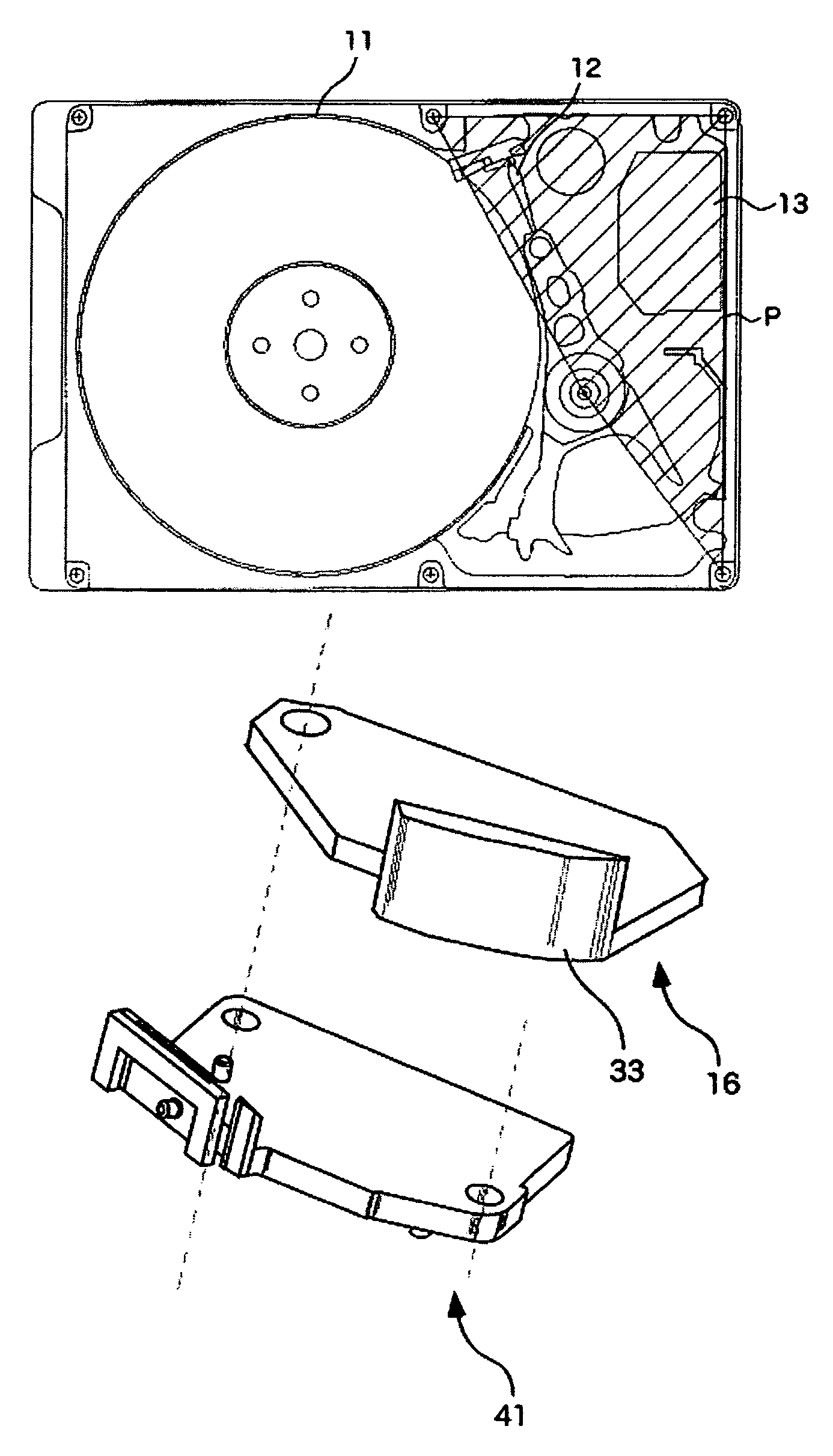
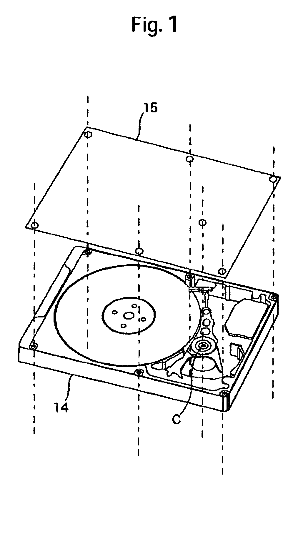
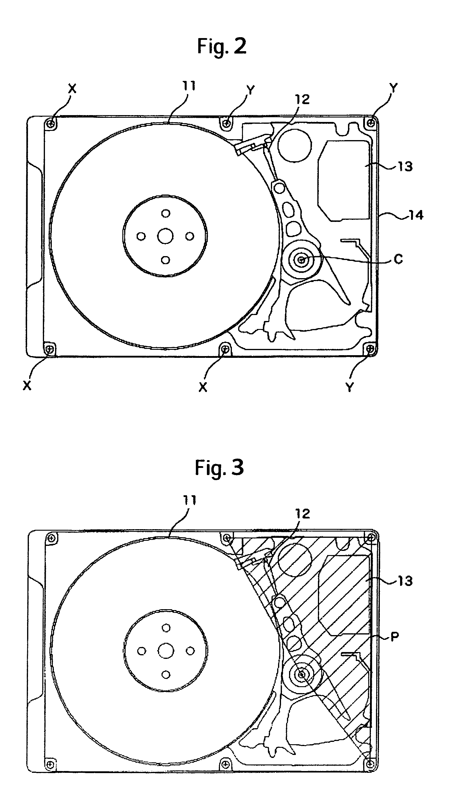
[0025]A specific embodiment of the present invention will be described with reference to the accompanying drawings. A disk drive according to the embodiment of the present invention includes a base 14 serving as a container and a top cover 15 as shown in FIG. 1. The base 14 basically accommodates a recording medium 11, a head assembly 12, and a circuit unit 13, as shown in FIG. 2. The head assembly 12 reads and writes data from and to the recording medium 11. The circuit unit 13 performs input and output of data to and from an external device. For the sake of explanation, FIGS. 1 and 2 show a condition, in which a vibration suppression member 16 to be described later is yet to be mounted.

[0026]The head assembly 12 is rotatably supported on a rotational axis C so as to allow a head portion to move radially over the recording medium 11. The top cover 15 covers the aforementioned portion of the base 14, in which the recording medium 11, the head assembly 12, and the circuit unit 13 are...


PUM

PropertyMeasurementUnit
flexibleaaaaaaaaaa
air pressureaaaaaaaaaa
areaaaaaaaaaaa

Abstract

Embodiments of the invention provide a disk drive suppressing a surface deformation of a top cover. In one embodiment, the disk drive includes a base and a top cover. The base accommodates a head assembly, a circuit unit, and a recording medium. The top cover is supported by the base at a plurality of inner points of support and peripheral edge points of support on a peripheral edge portion near a portion accommodating the head assembly and the circuit unit. The top cover covers the accommodating portion of the base. A vibration suppression member for suppressing vibration of the top cover is disposed in a polygon. The polygon has, as vertices, a plurality of inner points of support and, among the peripheral edge points of support, the peripheral edge points of support near the portion accommodating the head assembly and the circuit unit. The vibration suppression member is disposed at a position in the polygonal portion corresponding to an area near a loop of vibration in a surface of the top cover.

Description

CROSS-REFERENCES TO RELATED APPLICATIONS[0001]This application claims priority from Japanese Patent Application No. JP2004-378114, filed Dec. 27, 2004, the entire disclosure of which is incorporated herein by reference.BACKGROUND OF THE INVENTION[0002]The present invention relates to a disk drive such as a hard disk drive.[0003]Typically, a disk drive, such as a hard disk drive, includes a recording medium, a head assembly for reading and writing data from and to the recording medium, and a circuit unit for performing input and output of data to and from an external device. The head assembly is rotatably supported such that a head portion thereof can radially move over the recording medium. Each of these components is accommodated in a base serving as a container. The portion of the base accommodating these components is covered with a top cover.[0004]The top cover is secured to the base on a peripheral edge thereof. The top cover is also secured to a rotational axis of the head ass...

Claims


Application Information

Patent Timeline
Patent Type & Authority Patents(United States)
IPC IPC(8): G11B33/08
CPCG11B33/121G11B25/043G11B33/08
Inventor SERIZAWA, KOHJITSUJINO, HITOSHITANIZAWA, HIROKAZUSUMIYA, TAKEJI
Owner WESTERN DIGITAL TECH INC
Why Eureka
Try Eureka