Vibratory plow

a vibration-absorbing plow and vibration-absorbing technology, which is applied in the field of vibration-absorbing plows, can solve the problems of limited speed at which devices can be operated, and the difficulty of enduring significant length of time for operators, and achieve the effect of reducing vibration transmission, being inexpensive to build and opera

Inactive Publication Date: 2009-06-16
TORO CO THE
View PDF28 Cites 13 Cited by
  • Summary
  • Abstract
  • Description
  • Claims
  • Application Information

AI Technical Summary

Benefits of technology

[0004]Among the advantages of the invention is that it provides a surface cutting or breaking assembly that minimizes the transmission of vibrations outside of assembly housing. Another advantage of the invention is that it provides such an assembly that is mechanically uncomplicated and inexpensive to build and operate.
[0005]Additional advantages of this invention will become apparent from an examination of the drawings and the ensuing description.EXPLANATION OF TECHNICAL TERMS
[0006]As used herein, the term “actuator” refers to a device that imparts linear or rotational motion to a component. The term “actuator” thus includes hydraulic actuators or cylinders, pneumatic actuators, motors, motorized drives, levers, springs, gear systems and combinations thereof.
[0007]Linear actuators generate a force that is directed along a line, whereas rotary actuators generate a force which is directed along an arc and / or is adapted to rotate a component about an axis of rotation.
[0008]As used herein, the term “motor” refers to an electric, hydraulic or electro-hydraulic rotary actuator.
[0009]As used herein, the term “front” and similar terms, when used in reference to a surface cutting or breaking assembly that is adapted to be pulled behind a vehicle (or a component of such an assembly), refers to the component of the assembly or the side or portion of such component or of the entire assembly that is nearest the towing vehicle when the assembly is being pulled in a straight line along the direction of travel of the vehicle.

Problems solved by technology

Consequently, these devices are limited in the speed at which they can be operated to cut into a surface or to break up pavement.
Generally, all of the prior art devices tend to transmit significant vibrations to the transport vehicle, making such work difficult for an operator to endure for a significant length of time.

Method used


Image

  • Vibratory plow
  • Vibratory plow
  • Vibratory plow

Examples


Embodiment Construction

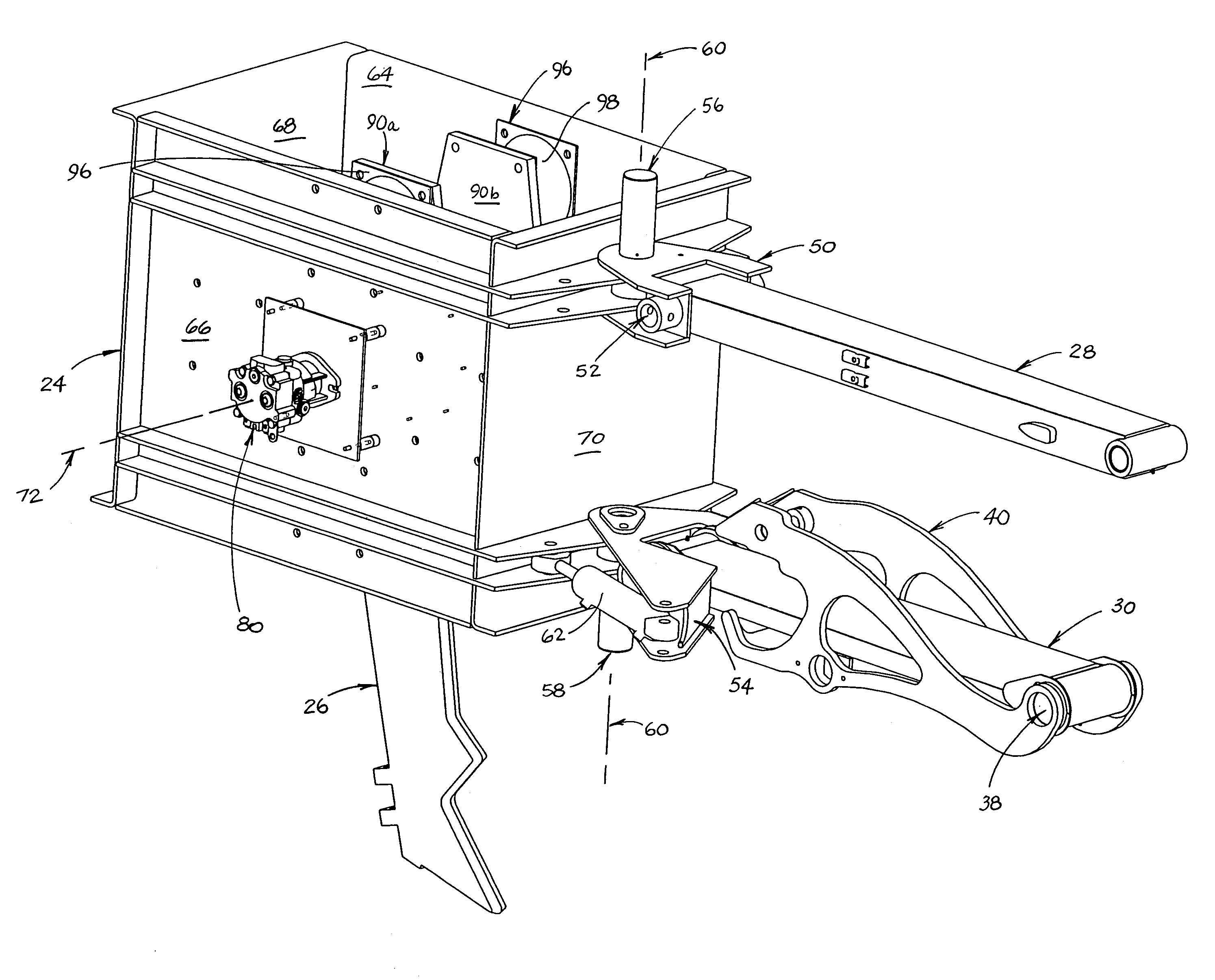
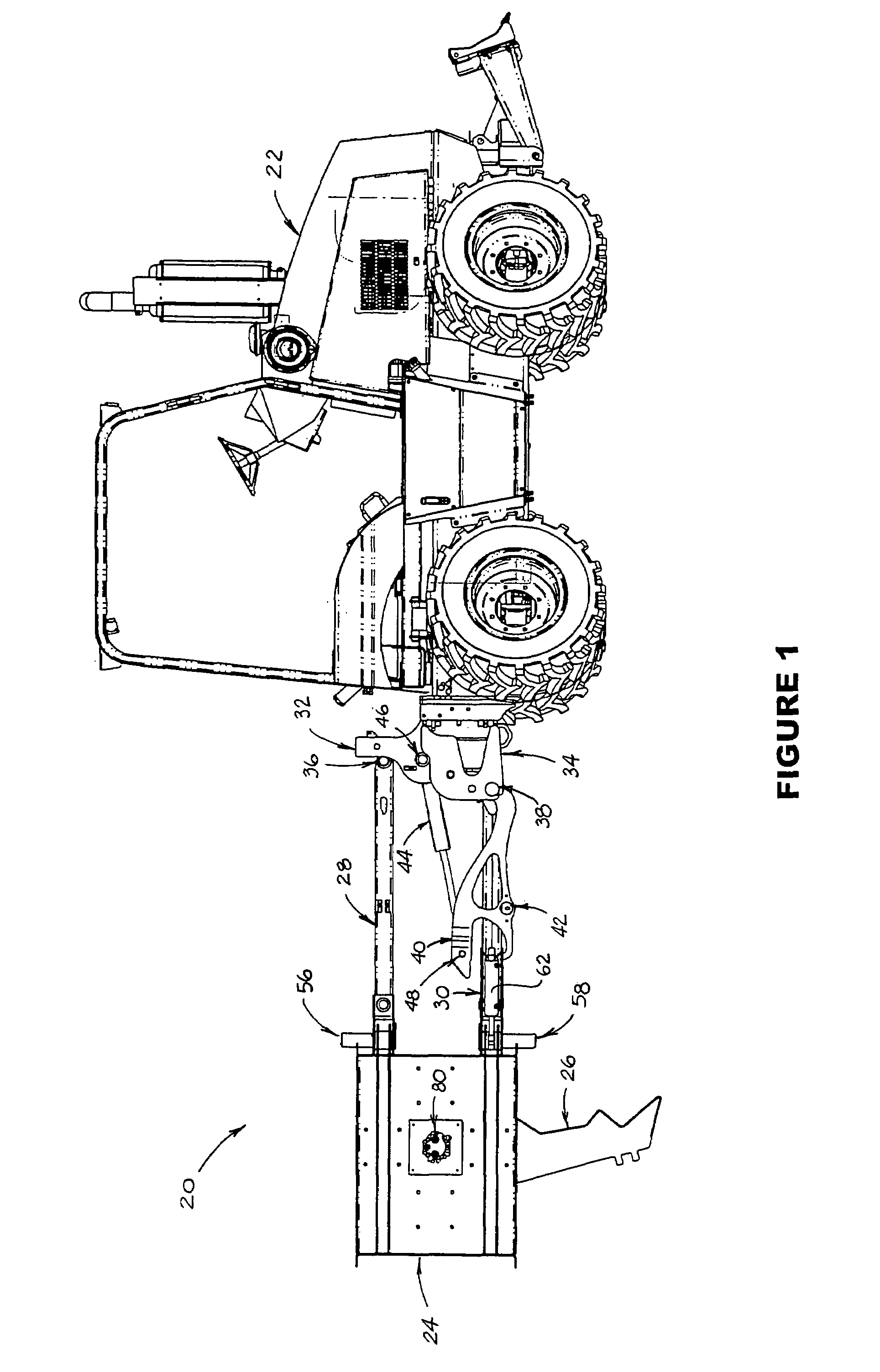
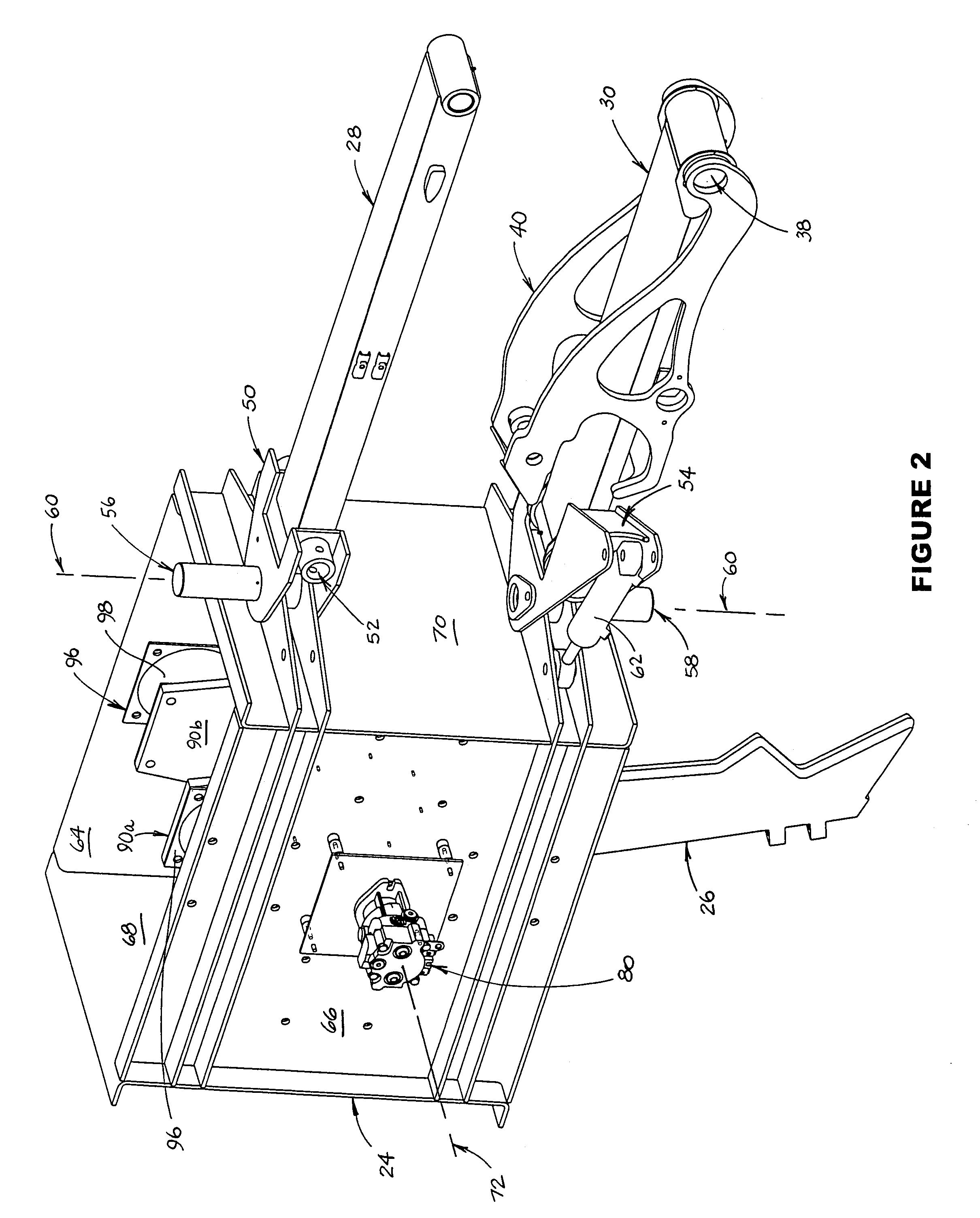
[0030]FIGS. 1-10 illustrate a preferred embodiment 20 of the plow assembly which is the subject of this invention. Preferred assembly 20 is adapted to be towed by a vehicle such as vehicle 22 (shown in FIG. 1), and includes housing 24, blade component 26 and a mounting assembly comprising upper and lower support arms 28 and 30, respectively. Attached to the rear of vehicle 22 is a mounting bracket comprised of upper portion 32 and lower portion 34. The forward end of upper support arm 28 is pivotally mounted on upper portion 32 of the mounting bracket at upper pivot 36, and the forward end of lower support arm 30 is pivotally mounted on lower portion 34 of the mounting bracket at lower pivot 38. An intermediate support arm 40 is also pivotally attached at its forward end to lower portion 34 of the mounting bracket at lower pivot 38. The rear end of intermediate support arm 40 is pivotally attached to lower support arm 30 at intermediate pivot 42. Actuator 44 is attached between pivo...


PUM


Abstract

A plow assembly includes a housing, a shaft having a first eccentricity and a shaft having a second eccentricity. The shaft having a first eccentricity is mounted within the housing for rotation about a first axis of rotation, and the shaft having a second eccentricity is mounted within the housing for rotation about a second axis of rotation. The assembly also includes a surface breaker blade and a balancing assembly. The surface breaker blade is mounted on the shaft having a first eccentricity in such a manner that rotation of the shaft having a first eccentricity causes the surface breaker blade to move in response to the first eccentricity of the shaft. The balancing assembly is mounted on the shaft having the second eccentricity in such a manner that rotation of the shaft having the second eccentricity causes the balancing assembly to move in response to the second eccentricity of the shaft. The assembly also includes a mechanism for rotating the shaft having a first eccentricity about the first axis of rotation, and a mechanism for rotating the shaft having a second eccentricity about the second axis of rotation.

Description

FIELD OF THE INVENTION[0001]This invention relates generally to an apparatus that may be used to cut into, break or plow a surface, including (but not limited to) a pavement surface, in preparation for the installation of pipes, cables and other utilities under the surface, or in connection with pavement installation or repair. More particularly, the invention relates to such an apparatus that is adapted to be mounted on or towed behind a vehicle to permit continuous plowing of the surface.BACKGROUND AND DESCRIPTION OF THE PRIOR ART[0002]It is frequently necessary to cut or break a surface, such as a dirt or clay surface which may have rocks and / or roots embedded therein or a paved surface such as an asphalt roadway, in order to permit the installation of utilities of various types. It is also necessary at times to remove portions of pavement from roadways and other paved surfaces in order to install such utilities or in preparation for repair or replacement of the pavement. Sometim...

Claims


Application Information

Patent Timeline
Patent Type & Authority Patents(United States)
IPC IPC(8): A01B35/00E02F5/10
CPCA01B11/00E01C23/124E02F5/326
Inventor DOERING, DAVIDCAMPBELL, THOMAS
Owner TORO CO THE
Why Eureka
Try Eureka