Push button switch

a push button switch and button technology, applied in the direction of electric switches, snap-action arrangements, electrical equipment, etc., can solve the problems of short life of the push button switch, not easy to accurately push the movable contact, etc., to achieve easy elastic deformation, accurate pressing, and not easy to wear out

Inactive Publication Date: 2009-06-16
ORMON CORP
View PDF6 Cites 70 Cited by
  • Summary
  • Abstract
  • Description
  • Claims
  • Application Information

AI Technical Summary

Benefits of technology

[0011]Since the guiding part and the reinforcing part are continuously provided at the edge of the through hole formed in the ceiling face of the cover, like the conventional technique, it is unnecessary to perform deep drawing. Consequently, roughening of the sliding face of the guiding part is suppressed, and the tip of the operating member that slides along the guiding part is not easily worn out, so that a long-life push button switch is obtained. In particular, by performing the press work so that roughening of the face is concentrated in the reinforcing part to avoid occurrence of roughening in the guiding part, a longer-life push button switch is obtained.

Problems solved by technology

It is not easy to accurately push the movable contact, and the operation characteristics tend to vary.
Consequently, the process face of the bent portion 35, in particular, the tilt surface with which the contact pressing portion 29 of the operating member 19 comes into press contact tends to become rough, and the operating member 19 sliding with the tilt surface wears easily, causing a problem such that the push button switch has short life.

Method used


Image

  • Push button switch
  • Push button switch
  • Push button switch

Examples


Embodiment Construction

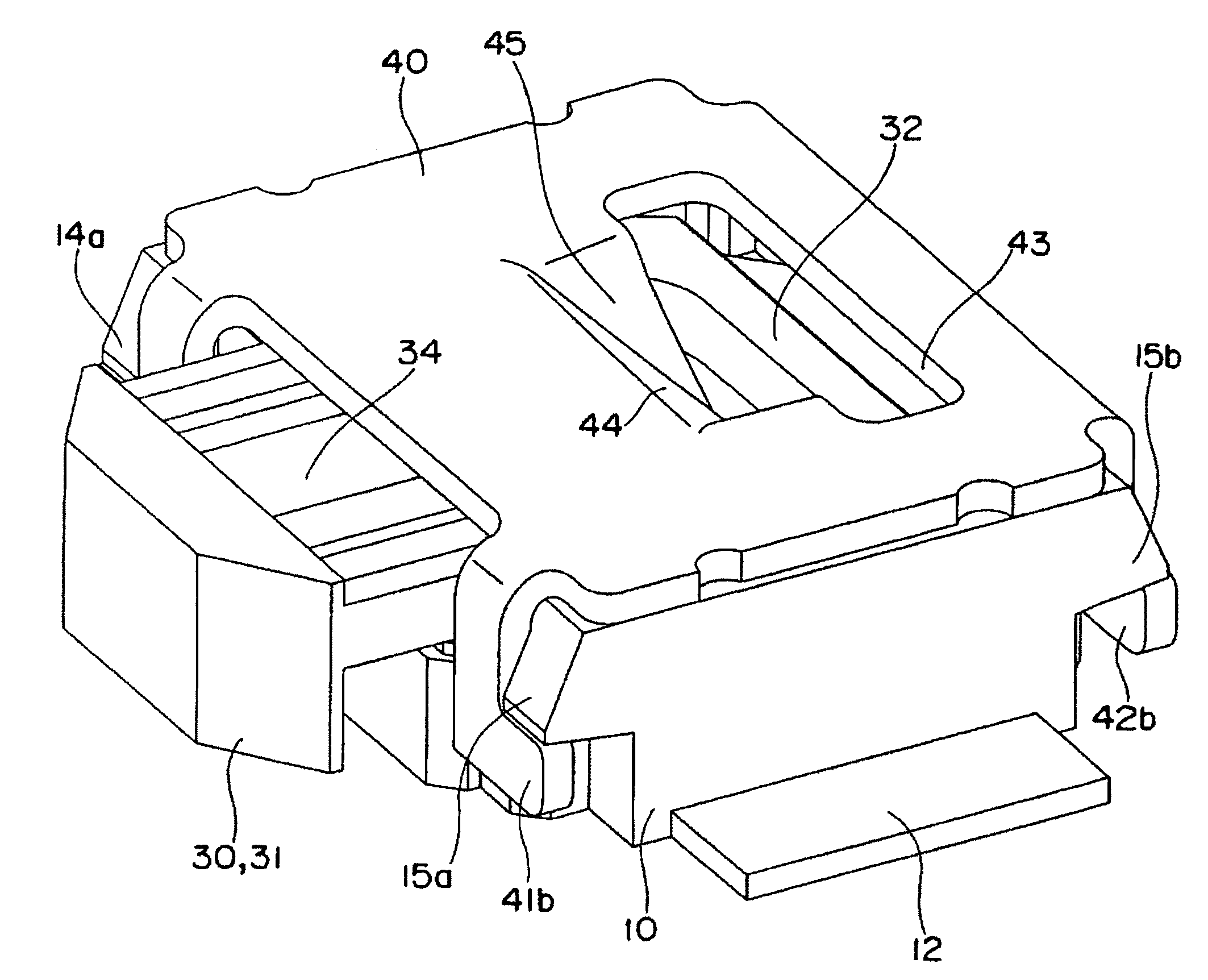
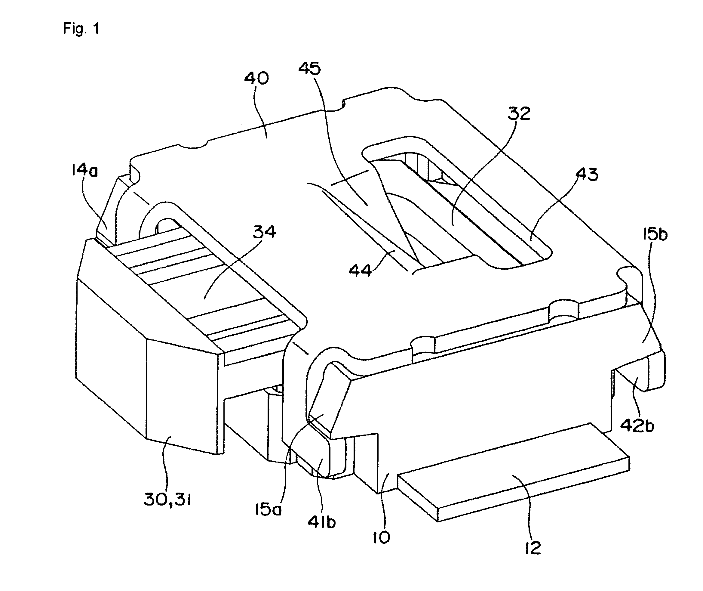
[0020]An embodiment of the present invention will be described with reference to the attached drawings of FIGS. 1 to 6.

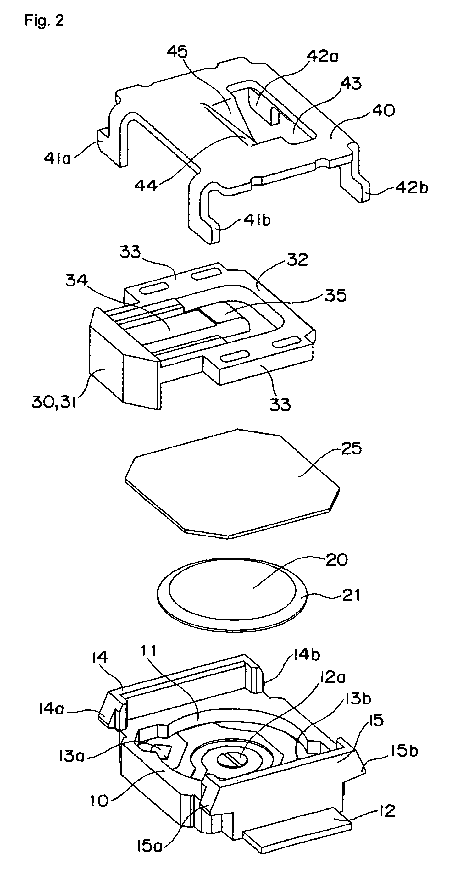
[0021]A push button switch as an embodiment is constructed by a base 10, a movable contact 20, an insulating sheet 25, an operating member 30, and a cover 40.

[0022]A recess 11 having an almost circular shape in plan view is formed in the center of the top face of the base 10, a central fixed contact 12a conducted to a fixed contact terminal 12 is provided so as to project in the center of the bottom face of the recess 11, and a pair of fixed contacts 13a and 13b conducted to a fixed contact terminal 13 are disposed in opposite positions while sandwiching the central fixed contact 12a. Guide ribs 14 and 15 are provided so as to project at both facing sides of the top face of the base 10. Further, the guide rib 14 has engagement projections 14a and 14b at its ends, and the guide rib 15 has engagement projections 15a and 15b at its ends.

[0023]The movable contact 20 is ...


PUM


Abstract

A push button switch has a housing formed by a base in which a fixed contact is disposed on a bottom face of the base and a cover assembled to the base, an operating member slidably inserted in the housing parallel to the bottom face of the base, a guiding part formed on the cover, extending obliquely inwards from a ceiling face of the cover, wherein a tip of an operating piece of the operating member is operable to slide along the guiding part, and a movable contact disposed in the housing and operable to be pressed against the fixed contact, thereby opening a circuit. The guiding part and a reinforcing part extending from the ceiling face of the cover at least on one side of the guiding part are formed at an edge of a through hole formed in the ceiling face of the cover. The movable contact has a thin dome shape.

Description

BACKGROUND OF THE INVENTION[0001]1. Field of the Invention[0002]The present invention relates to a push button switch and, more particularly, to a push button switch in which an operating member is inserted in the axial direction to open / close a contact.[0003]2. Description of the Related Art[0004]Hitherto, there is a push button switch in which an operating member assembled in a housing is pushed from a side to depress a movable contact to come into contact with a fixed contact, thereby opening / closing a circuit. For example, there is a push button switch in which a tilt piece 33 having a cantilever shape is cut from a center of the flat surface of a cover member 17 constructing a housing and an operating part 34 of an operating member 16 is pressed against the tilt piece 33, thereby depressing a movable contact 14 to open a circuit (refer to Japanese Unexamined Utility Model Publication No. Hei 5-83958).[0005]There is another push button switch having a bent portion 35 in an almos...

Claims


Application Information

Patent Timeline
Patent Type & Authority Patents(United States)
IPC IPC(8): H01H5/18
CPCH01H13/48H01H2013/525
Inventor NAGATA, KENSHI
Owner ORMON CORP
Why Eureka
Try Eureka