Method for making a data storage device

a data storage device and magnetic disc technology, applied in the direction of casings/cabinets/drawers, instruments, casings/cabinets/drawers, etc., can solve the problems of requiring extra parts, wasting a large amount of this limited space or “height” and slowing down the search time, so as to reduce the complexity and time, the effect of minimizing the wasted space in the interior

Inactive Publication Date: 2009-06-23
SEAGATE TECH LLC
View PDF23 Cites 5 Cited by
  • Summary
  • Abstract
  • Description
  • Claims
  • Application Information

AI Technical Summary

Benefits of technology

[0012]The present invention relates to a disc drive having a molded top cover that includes an embedded or “over-molded” top pole piece that cooperates with other components of a voice coil motor assembly attached to a base plate of the disc drive. The over-molded top pole piece minimizes wasted space within the interior of the drive and reduces the complexity and time required to assemble the voice coil motor assembly.

Problems solved by technology

One of the problems with this conventional design is that the overall height of the disc drive 100 is fixed due to form factor limitations, and thus a portion of this limited space or “height” is wasted due to the inclusion of the air gap 123.
A second problem with this conventional design is that it requires extra parts, such as standoffs 130, to both mount and properly position the top pole 124 within the head disc assembly.
Because a quick change in current through the coil 122 is necessary for fast seek times, it is axiomatic that an increase in inductance within the coil results in slower seek times. In addition to adding to the complexity and cost of manufacturing a disc drive, a further problem with the standoffs 130 is that engineering tolerances in the manufacture of the standoffs can lead to variations in the magnetic fields produced by different voice coil motors 120
However, adhesives are expensive and may cause outgassing that can corrupt normal disc drive operation, while welding creates the potential for gaps to form between the two parts that may allow contaminants to be trapped and possibly escape to the interior of the head disc assembly.
In any event, the process of attaching the top pole 124 to the top cover 104 requires extra manufacturing steps that increases the build time and thus the cost of a disc drive 100.
As a result, it is difficult to provide a smooth mounting surface on the inner surface of the top cover 104 for attaching to the top pole 124.
Indeed, while a metal top cover 104 provides needed support for certain disc drive components such as the bearing shaft assembly 112, it is expensive to mold or stamp aluminum top covers 104 with the intricate shapes required by current disc drive designs.

Method used


Image

  • Method for making a data storage device
  • Method for making a data storage device
  • Method for making a data storage device

Examples


Embodiment Construction

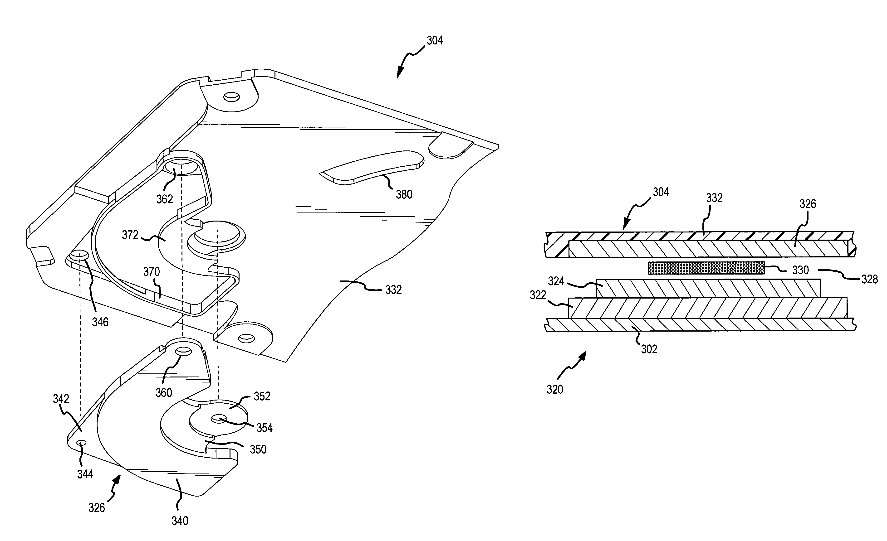
[0025]A preferred embodiment of the present invention is shown in FIGS. 3-5. A disc drive 300 (FIG. 3) includes a base plate 302 and a top cover 304 formed from a moldable material such as a reinforced polymer plastic. The top cover 304, described in greater detail below, connects to the base plate 302 to form an internal, sealed environment for the disc drive 300 similar to that shown in FIG. 1 above. The internal components of the drive 300 include a drive spindle motor 306 that rotates one or more discs 308, and an actuator assembly 310 that rotates about a bearing shaft 312 during a seek operation. The spindle motor 306 is preferably of a rotating shaft design that does not require a connection to the top cover 304 (as in the case of a stationary shaft design). The actuator assembly 310 includes a plurality of actuator arms 314 with one or more flexures 316 extending from each of the actuator arms 314 towards the discs 308. Read / write heads 318 mounted at the distal end of each ...


PUM

PropertyMeasurementUnit
thicknessaaaaaaaaaa
moldableaaaaaaaaaa
speedaaaaaaaaaa

Abstract

A data storage device is made by molding a portion of a motor into a first enclosure member, and then coupling the first enclosure member to a second enclosure member to define an interior environment for other data storage device components.

Description

RELATED APPLICATIONS[0001]This application is a divisional application of U.S. patent application Ser. 10 / 326,790, filed Dec. 20, 2002, now abandoned, and claims priority from U.S. provisional application Ser. No. 60 / 383,035, filed May 23, 2002.FIELD OF THE INVENTION[0002]This application relates generally to magnetic disc drives, and more particularly to a disc drive having a molded top cover where a top pole of a voice coil motor assembly is over-molded within the molded top cover of the disc drive.BACKGROUND OF THE INVENTION[0003]Disc drives are data storage devices that store digital data in magnetic form on a rotating storage medium, such as a disc. Modem disc drives include a head disc assembly comprising one or more rigid discs that are coated with a magnetizable medium and mounted on the hub of a drive motor for rotation at a constant high speed. Disc drive components within the head disc assembly, such as the hub of the drive motor, an actuator assembly, and a voice coil mo...

Claims


Application Information

Patent Timeline
Patent Type & Authority Patents(United States)
IPC IPC(8): H05K7/14G11B33/04G11B25/04G11B33/12
CPCG11B25/043G11B33/121Y10T29/49027Y10T29/49009Y10T29/49025
Inventor TEO, JOO YONGJIERAPIPATANAKUL, NIROOTCHEE, WAIONNONG, BOONSENG
Owner SEAGATE TECH LLC
Why Eureka
Try Eureka