Flow control device

a flow control and flow rate technology, applied in the direction of fluid tightness measurement, process and machine control, instruments, etc., can solve the problems of device being stolen, difficult to individually grasp the flow rate of water consumed in each of the stools and wash stands, and complicated device structure, etc., to facilitate construction, maintenance, and management. , to achieve the effect of easy grasping the over and short of fluid

Active Publication Date: 2009-06-23
KIMURA GIKEN KK
View PDF14 Cites 26 Cited by
  • Summary
  • Abstract
  • Description
  • Claims
  • Application Information

AI Technical Summary

Benefits of technology

[0013]Moreover, the flow control device of the present invention suppresses consumption of the electricity by supplying the electricity generated by itself to the control device as described above. In addition, installation of an external power supply is substantially unnecessary for the control device or the like, so in installation of the flush valve device, it is also possible to extensively improve the construction property thereof.
[0047]As described above, according to the present invention, it is possible to provide the flow control device having the power-saving effect in addition to the water-saving effect. Further, it is possible to provide the flow control device which also facilitates construction, maintenance, and management.

Problems solved by technology

Therefore, the device tends to be complicated in structure as compared to the manual water stop valve.
Besides, the flush valve device of this type may obtain the high water-saving effect, so there is a fear of the device being stolen.
However, the water meter indicates a flow rate in the whole facility including both stools and wash stands, so it was difficult to individually grasp the flow rate of the water consumed in each of the stools and the wash stands.

Method used


Image

  • Flow control device
  • Flow control device
  • Flow control device

Examples


Embodiment Construction

[0065]In the following, a preferred embodiment of the present invention is described with reference to the drawings.

[0066]In this embodiment, the description is made by taking, as an example, a flush valve unit (flow control device) to which a flush valve device is applied as a water stop valve for a stool.

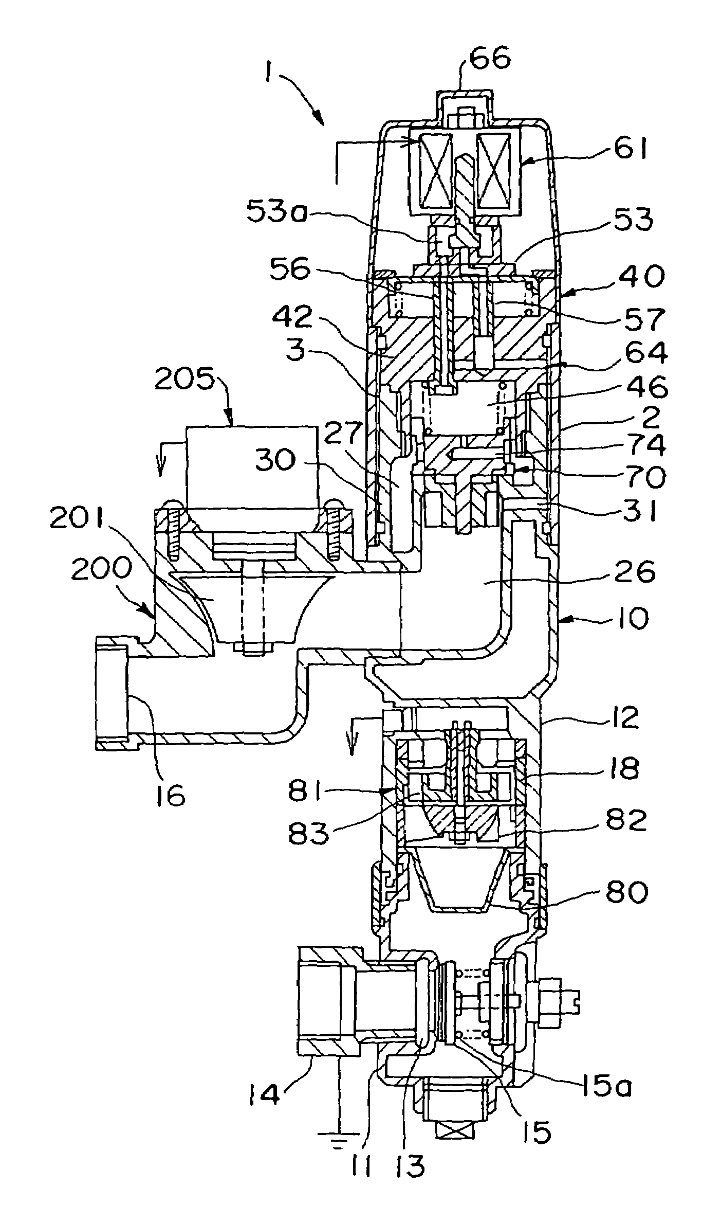
[0067]As shown in an entire longitudinal sectional view of FIG. 3, a flush valve device 1 includes a first valve housing 10 and a second valve housing 40 which are connected to each other by a sleeve 2 and an external housing 200 connected to the second valve housing 40.

[0068]The first valve housing 10 is composed of an inlet side block 11 and an outlet side block 12. The inlet side block 11 includes an inlet 13 on a lower portion. The inlet 13 is connected to an inflow tube 14. The inlet 13 is provided with a check valve 15, which opens and closes due to a water pressure of the washing water supplied from the inflow tube 14, being biased toward a closing direction by a coil sprin...


PUM


Abstract

A flow control device having a power saving effect in addition to a water saving effect. Further, another object is to provide a flow control device easy to install, maintain and manage. The flow control device of the invention comprises a flush valve device having a main control valve in a path leading from an inlet to an outlet, a flowmeter unit for converting the presence or absence of flow of washing water leading from the inlet to the outlet into a pulse signal and outputting the latter, a control device for controlling the opening and closing of the main control valve according to the output of the flowmeter unit, and a power generating unit for generating power by using the flow of the washing water as power, wherein at least part of the power obtained in the power generating unit is supplied to the control device.

Description

TECHNICAL FIELD[0001]The present invention relates to a flow control device of an automatic water stop type for use in a water section such as a stool.BACKGROUND ART[0002]An example of a flow control device of this type includes a device equipped with a flush valve device disclosed in JP 07-189311 A, which was previously filed by the applicant of the present invention.[0003]In particular, the flow control device includes a main control valve arranged in a path leading from an inlet to an outlet, a pressure chamber positioned behind the main control valve and has therein a spring for biasing the main control valve toward a valve seat while keeping a balance with respect to the inlet side, a pilot valve for allowing the main control valve to open by releasing pressure in the pressure chamber, and a flowmeter unit 81 for measuring a flow rate of water flowing from the inlet to the outlet. Based on an output of the flowmeter unit, a valve opening of the pilot valve is automatically cont...

Claims


Application Information

Patent Timeline
Patent Type & Authority Patents(United States)
IPC IPC(8): G05D16/20E03D3/02G01M3/28
CPCE03D3/02G01M3/2807G05D7/0635Y10T137/7761E03D3/00
Inventor KIMURA, MOTOYASUKIMURA, TOMOEI
Owner KIMURA GIKEN KK
Why Eureka
Try Eureka