Electric flight control surface actuation system for aircraft flaps and slats

a technology of flight control surface and actuator, which is applied in the direction of aircraft transmission means, aircraft components, aircraft power plants, etc., can solve the problems of system complexity, system drawbacks, and inoperable flight control surface actuators

Active Publication Date: 2009-06-23
HONEYWELL INT INC
View PDF29 Cites 27 Cited by
  • Summary
  • Abstract
  • Description
  • Claims
  • Application Information

AI Technical Summary

Benefits of technology

[0008]The present invention provides a relatively lightweight flight control surface actuation system for aircraft flaps and slats.

Problems solved by technology

Though unlikely, it is postulated that a flight control surface actuator could become inoperable.
Although the flight control surface actuation systems that use central flap and slat drive units are generally safe, reliable, and robust, these systems do suffer certain drawbacks.
Namely, these systems can be relatively complex, can involve the use of numerous parts, and can be relatively heavy.

Method used


Image

  • Electric flight control surface actuation system for aircraft flaps and slats
  • Electric flight control surface actuation system for aircraft flaps and slats
  • Electric flight control surface actuation system for aircraft flaps and slats

Examples


Embodiment Construction

[0014]The following detailed description of the invention is merely exemplary in nature and is not intended to limit the invention or the application and uses of the invention. Furthermore, there is no intention to be bound by any theory presented in the preceding background of the invention or the following detailed description of the invention.

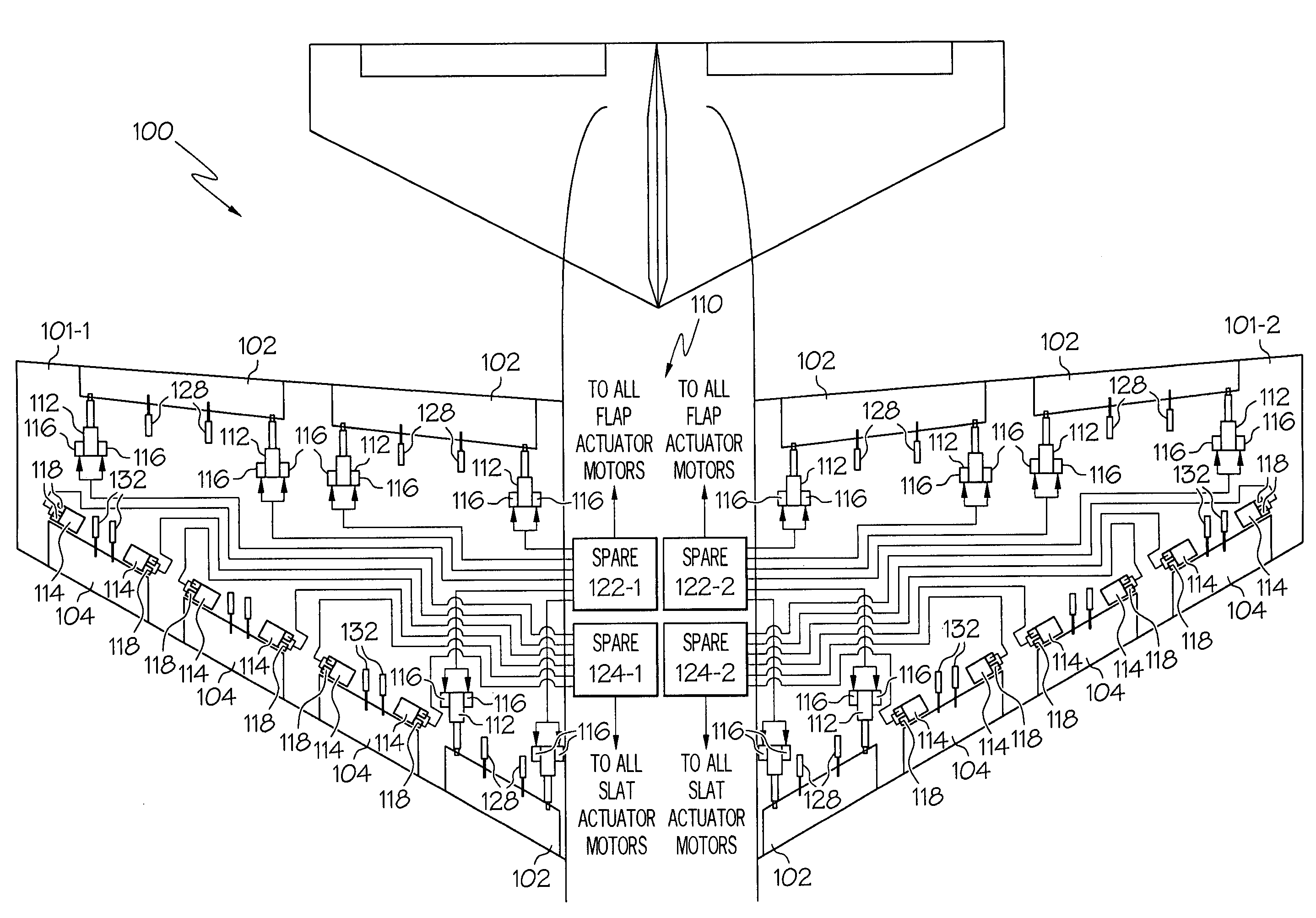
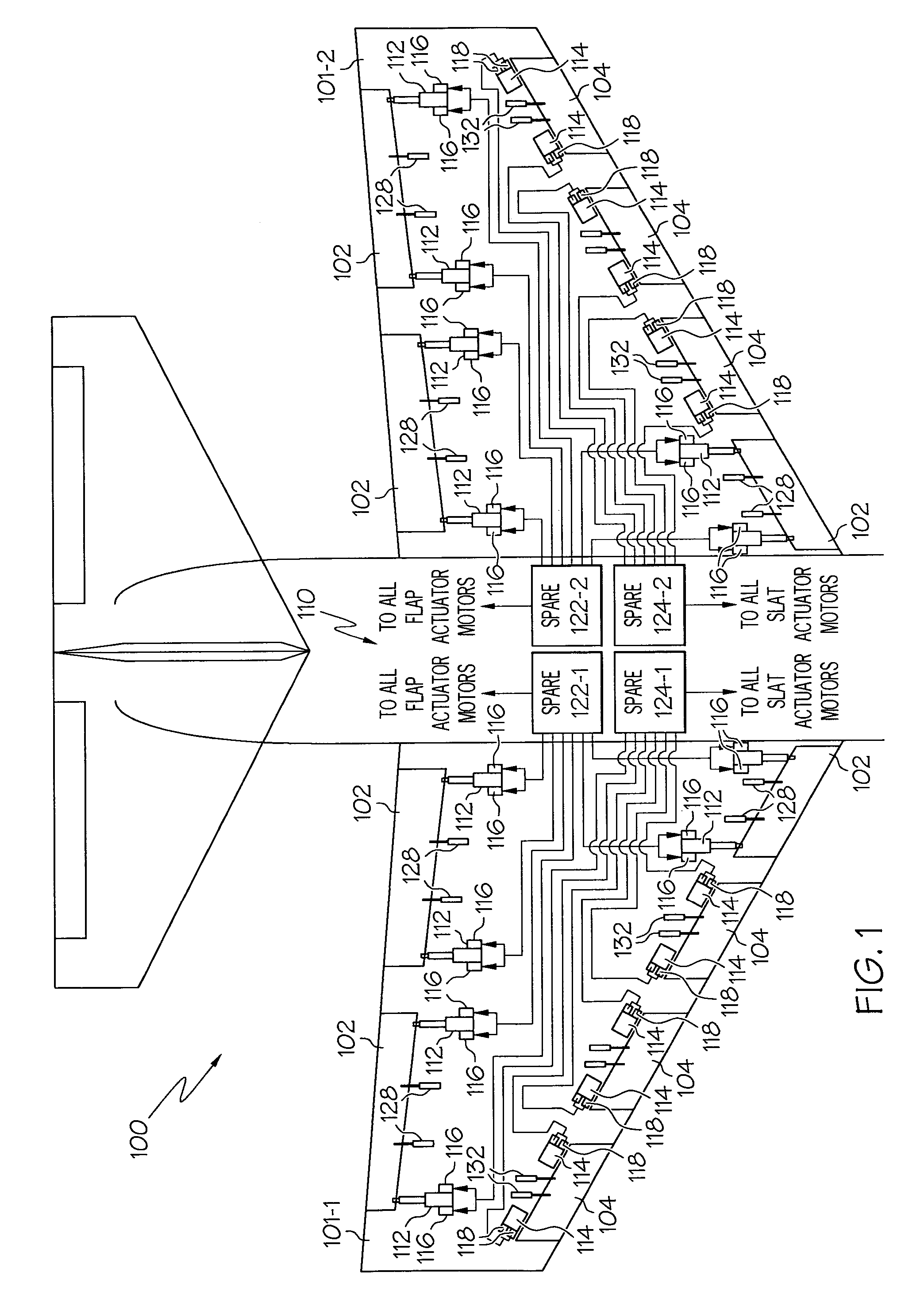
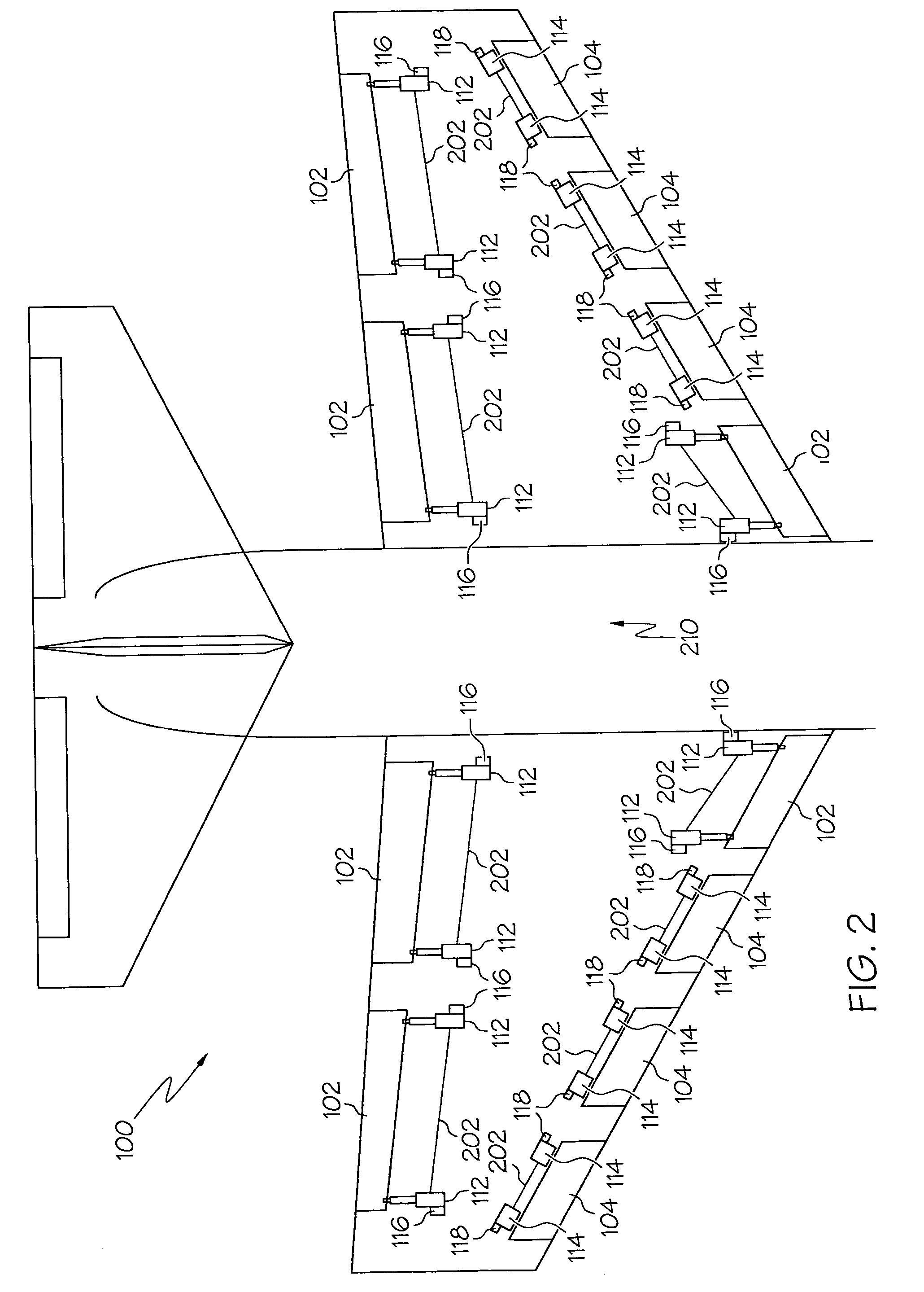
[0015]Turning first to FIG. 1, a schematic diagram of a portion of an exemplary aircraft 100 depicting an exemplary embodiment of a flight control surface actuation system 110 for aircraft flaps and slats is provided. The aircraft 100 includes a plurality of control surfaces on each wing 101 (101-1, 101-2), namely a plurality of flaps 102 and a plurality of slats 104. In the depicted embodiment, the aircraft 100 includes not only a plurality of trailing edge flaps 102, but additionally includes a leading edge flap 102, sometimes referred to as a Krueger flap, on each wing 101. It will be appreciated, however, that this is merely exemplary, a...


PUM


Abstract

An aircraft flight control surface actuation system includes a plurality of electric motors-driven flap actuators, and a plurality of electric motor-driven slat actuators. The motor-driven actuators receive activation signals from flap and slat actuator controllers and is, in response to the activation signals, move the flaps and slats between stowed and a deployed positions. The flap and slat actuator controllers each include a plurality of independent actuator control channels that independently supply the activation signals to the motor-driven actuators.

Description

CROSS-REFERENCES TO RELATED APPLICATIONS[0001]This application claims the benefit of U.S. Provisional Application No. 60 / 694,640, filed Jun. 27, 2005.TECHNICAL FIELD[0002]The present invention relates to flight surface actuation and, more particularly, to an electric flight surface actuation system for aircraft flaps and slats.BACKGROUND[0003]Aircraft typically include a plurality of flight control surfaces that, when controllably positioned, guide the movement of the aircraft from one destination to another. The number and type of flight control surfaces included in an aircraft may vary, but typically include both primary flight control surfaces and secondary flight control surfaces. The primary flight control surfaces are those that are used to control aircraft movement in the pitch, yaw, and roll axes, and the secondary flight control surfaces are those that are used to influence the lift or drag (or both) of the aircraft. Although some aircraft may include additional control sur...

Claims


Application Information

Patent Timeline
Patent Type & Authority Patents(United States)
IPC IPC(8): B64C13/50
CPCB64C13/503B64C13/505
Inventor HANLON, CASEYWINGETT, PAUL T.POTTER, CALVIN C.
Owner HONEYWELL INT INC
Why Eureka
Try Eureka