
Headrest adjusting structure for a seat

a technology for adjusting structures and seats, applied in the field of headrest adjusting structures for seats, to achieve the effect of simple operation

Inactive Publication Date: 2009-06-23
CHOU KUO CHING +1
View PDF10 Cites 71 Cited by
  • Summary
  • Abstract
  • Description
  • Claims
  • Application Information

AI Technical Summary

Benefits of technology

[0005]In view of the inconvenience associated with use of existing headrests installed on an upper end of a seat, the present invention provides an improvement in which a headrest installed at an upper end of a seat can be adjusted in position and angle as needed by a simple operation.
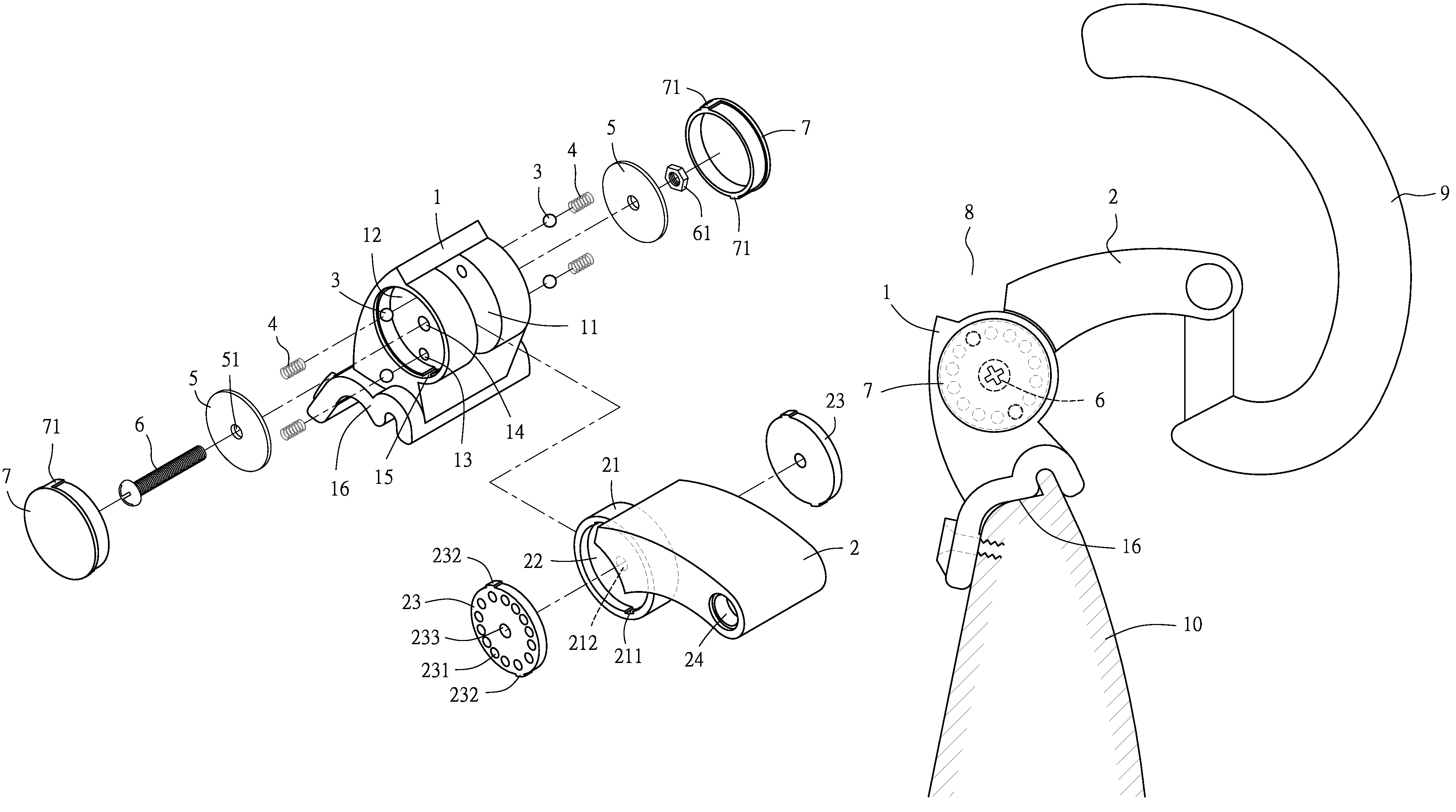
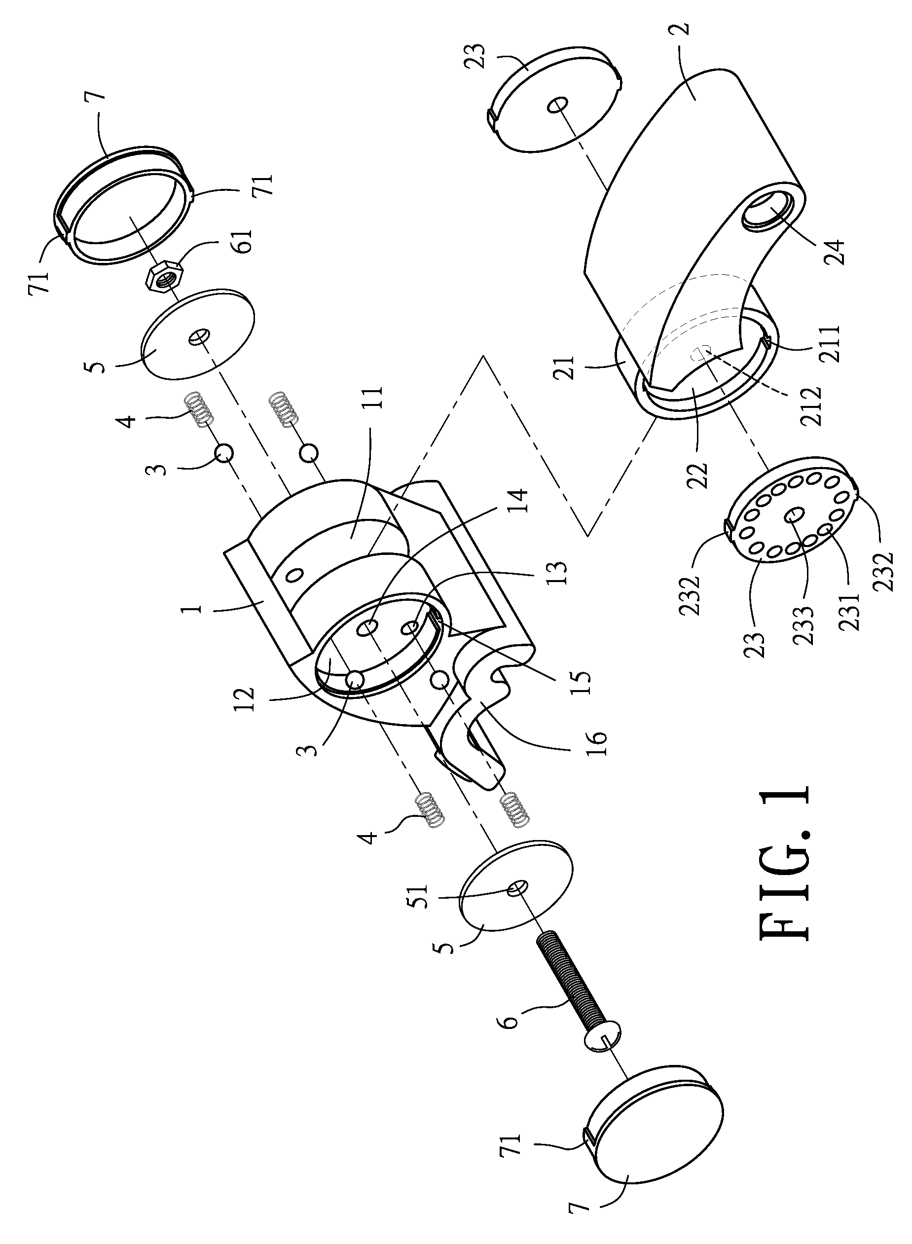
[0006]A first objective of the present invention is to provide a headrest adjusting structure for a seat comprising a base and a rotating support. The base is formed with a groove for receiving a supporting portion formed at a first end of the rotating support, wherein the supporting portion has outwardly opening cavities, each of which can receive and retain a positioning disk having a plurality of recesses on a side surface thereof and at least one protrusion on a periphery of the positioning disk for engaging with a corresponding dent formed on the supporting portion. The base further has outwardly opening accommodating spaces on two sides thereof respectively, wherein each of the accommodating spaces is formed with an aperture on a surface thereof for receiving a ball and a resilient element. Each of the balls has an end engageable in the corresponding recess on the corresponding positioning disk mounted in the rotating support while a pressing plate is fitted in each of the accommodating spaces to retain the resilient element and the ball. A threaded fastener can be penetratingly coupled with the pressing plates fitted in the accommodating spaces on the two sides of the base, the base and the supporting portion formed at the end of the rotating support, and be further combined with a nut to position and hold together the pressing plates, the base and the supporting portion. In addition, an outer cap is mounted on each of the accommodating spaces formed on the two sides of the base. A headrest adjusting assembly thus formed can be installed on a seat so that a headrest combined to an end of the headrest adjusting assembly can be easily adjusted to a preferred position by manually pulling the rotating support.

Problems solved by technology

However, such a headrest is usually extending from an upper end of a seat at a single and fixed angle and cannot be adjusted to a desired angle or height according to the head positions of different users.

Method used


Image

  • Headrest adjusting structure for a seat
  • Headrest adjusting structure for a seat
  • Headrest adjusting structure for a seat

Examples


Embodiment Construction

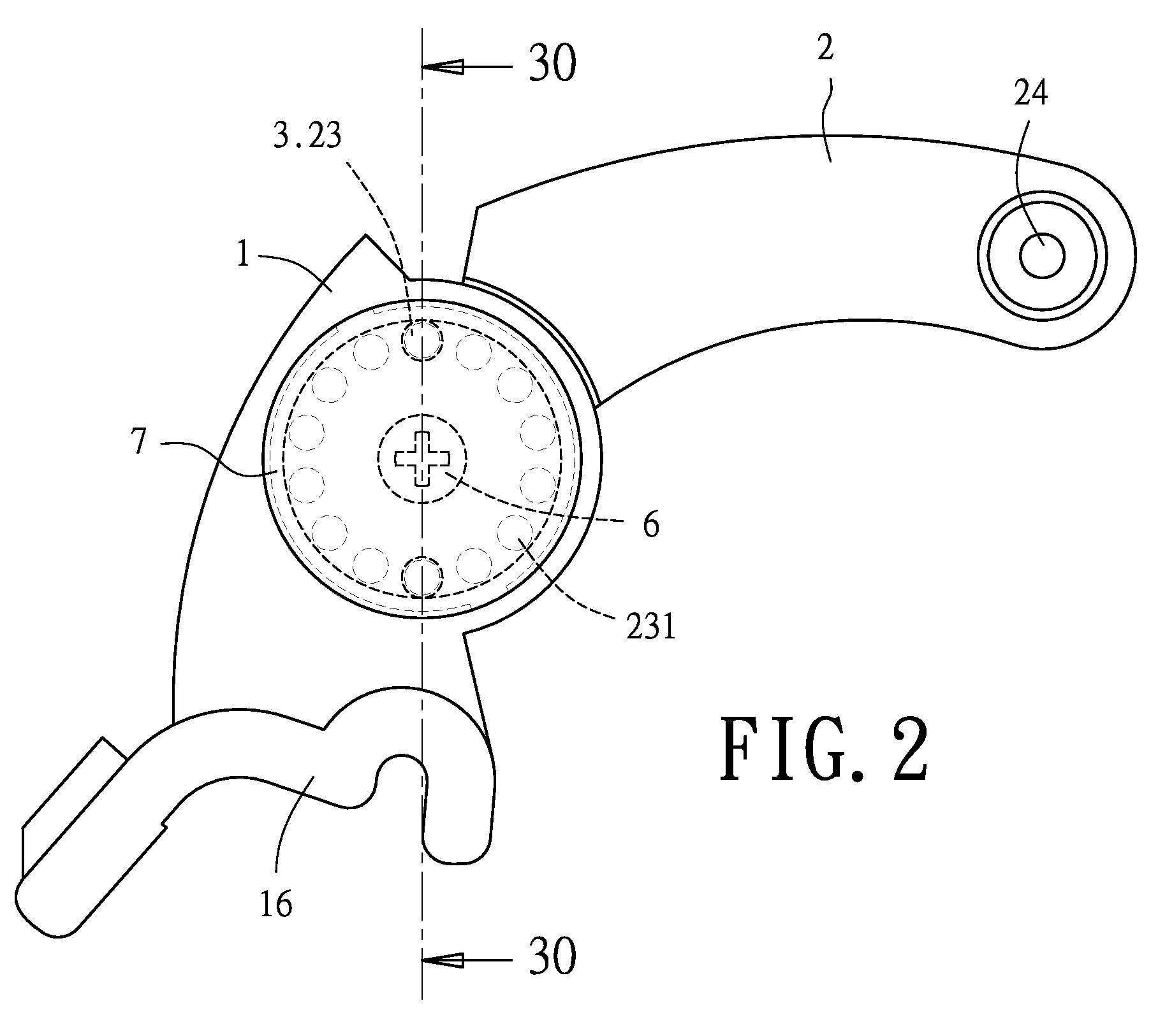
[0017]Referring to FIG. 1, a headrest adjusting structure for a seat according to the present invention comprises a base 1 and a rotating support 2 which form a headrest adjusting assembly 8.

[0018]The base 1 is formed with a groove 11 and has outwardly opening accommodating spaces 12 on two sides of the base 1, respectively, wherein each of the accommodating spaces 12 is provided on a surface thereof with apertures 13 for each receiving a ball 3 and a resilient element 4. (In this embodiment, two apertures 13 are provided on the surface of each said accommodating space 12, although there can be only one or more than two apertures 13 on the surface of each said accommodating space 12.) A pressing plate 5 is fitted in each of the accommodating spaces 12 for retaining the corresponding resilient elements 4 and balls 3. The base 1 has a through hole 14 in a center thereof so that a threaded fastener 6 can penetrate a hole 51 on each of the pressing plates 5 fitted in the accommodating s...


PUM


Abstract

A headrest adjusting structure for a seat comprises a base and a rotating support. The base is formed with a groove for receiving a supporting portion of the rotating support which has outwardly cavities. The base has outwardly accommodating spaces which is formed with an aperture for receiving a ball and resilient element on two sides. Each ball has an end engageable with the corresponding recess on the positioning disk mounted in the rotating support. A threaded fastener can penetrate the pressing plates fitted in the accommodating spaces of the base, the base and the supporting portion of the rotating support, and be screwed into a nut to hold together. A cap is mounted on each accommodating space of the base. A headrest which is combined at the headrest adjusting assembly installed on a seat can be adjusted to a preferred position by manually pulling the rotating support easily.

Description

BACKGROUND OF THE INVENTION[0001]1. Technical Field[0002]The present invention relates to a headrest adjusting structure for a seat, and more particularly, to a headrest adjusting structure installed at an upper end of a seat designed for comfortable sitting, wherein a headrest combined at an end of the headrest adjusting structure can be easily adjusted to a preferred position and angle by operating the headrest adjusting structure.[0003]2. Description of Related Art[0004]Nowadays, seats available on the market are designed not only for a user to simply sit in or on for a rest, but also to put his or her head on a headrest extending from an upper end of the seat, so that the user can sit more comfortably in or on the seat with his or her head supported by the headrest. However, such a headrest is usually extending from an upper end of a seat at a single and fixed angle and cannot be adjusted to a desired angle or height according to the head positions of different users.SUMMARY OF ...

Claims


Application Information

Patent Timeline
Patent Type & Authority Patents(United States)
IPC IPC(8): A47C7/38A47C7/36
CPCA47C7/38
Inventor CHOU, KUO-CHINGCHOU, DING-KUO
Owner CHOU KUO CHING
Learn More