Semiconductor light source configured as a light tube

a technology of semiconductors and light sources, applied in the direction of light control, spectral modifiers, light support devices, etc., can solve the problems of personnel hazards, mercury vapor and fluorescent materials present environmental problems, and fluorescent light sources tend to fail completely without warning

Inactive Publication Date: 2009-06-23
DOCUMENT SECURITY SYST
View PDF11 Cites 47 Cited by
  • Summary
  • Abstract
  • Description
  • Claims
  • Application Information

AI Technical Summary

Benefits of technology

[0015]The manner in which the present invention provides its advantages can be more easily understood with reference to FIGS. 1 and 2, which illustrate a light source according to one embodiment of the present invention. FIG. 1 is a prospective view of light source 50, and FIG. 2 is a cross-sectional view of light source 50. Light source 50 includes an LED light source 51 and a tube 52. Tube 52 is constructed from a transparent medium that contains scattering particles 54. The light from light source 51 enters tube 52 at an angle 53 such that most of the light is incident on the walls of tube 52 at angles R that are greater than the critical angle, and hence, suffers total internal reflection. In the absence of the scattering particles 54, this light would remain trapped in tube 52 until it exited tube 52 at the end 57 opposite to that at which the light is injected by light source 52. Scattering particles 54 are dispersed in the tube at a density such that some of the light is scattered by the particles and strikes the wall of tube 52 at angles that are less than the critical angle. This light escapes tube 52 as shown at 55.

Problems solved by technology

In addition, fluorescent light sources tend to fail completely without warning.
Both the mercury vapor and fluorescent materials present environmental problems when inoperative fluorescent tubes must be replaced.
In addition, these materials present personnel hazards when a tube is accidentally broken during replacement.
These transformers represent a significant cost and present fire hazards.
Furthermore, fluorescent light fixtures with adjustable intensities are difficult to construct, and hence, the user can only control the level of light in a room by turning on or off specific light fixtures.
Unfortunately, LEDs are inherently point light sources, and hence, these light sources appear as a string of bright “dots” rather than a uniformly illuminated tube.
While the bright dots can be muted somewhat by including scattering material within or on the surface of the tube, the result is still a poor substitute for a fluorescent tube.

Method used


Image

  • Semiconductor light source configured as a light tube
  • Semiconductor light source configured as a light tube
  • Semiconductor light source configured as a light tube

Examples


Embodiment Construction

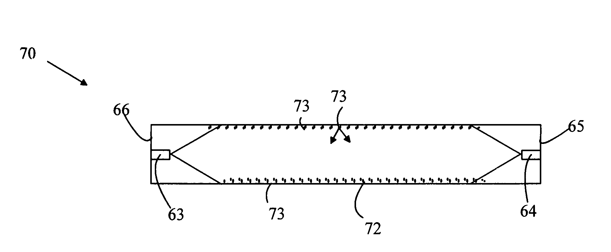
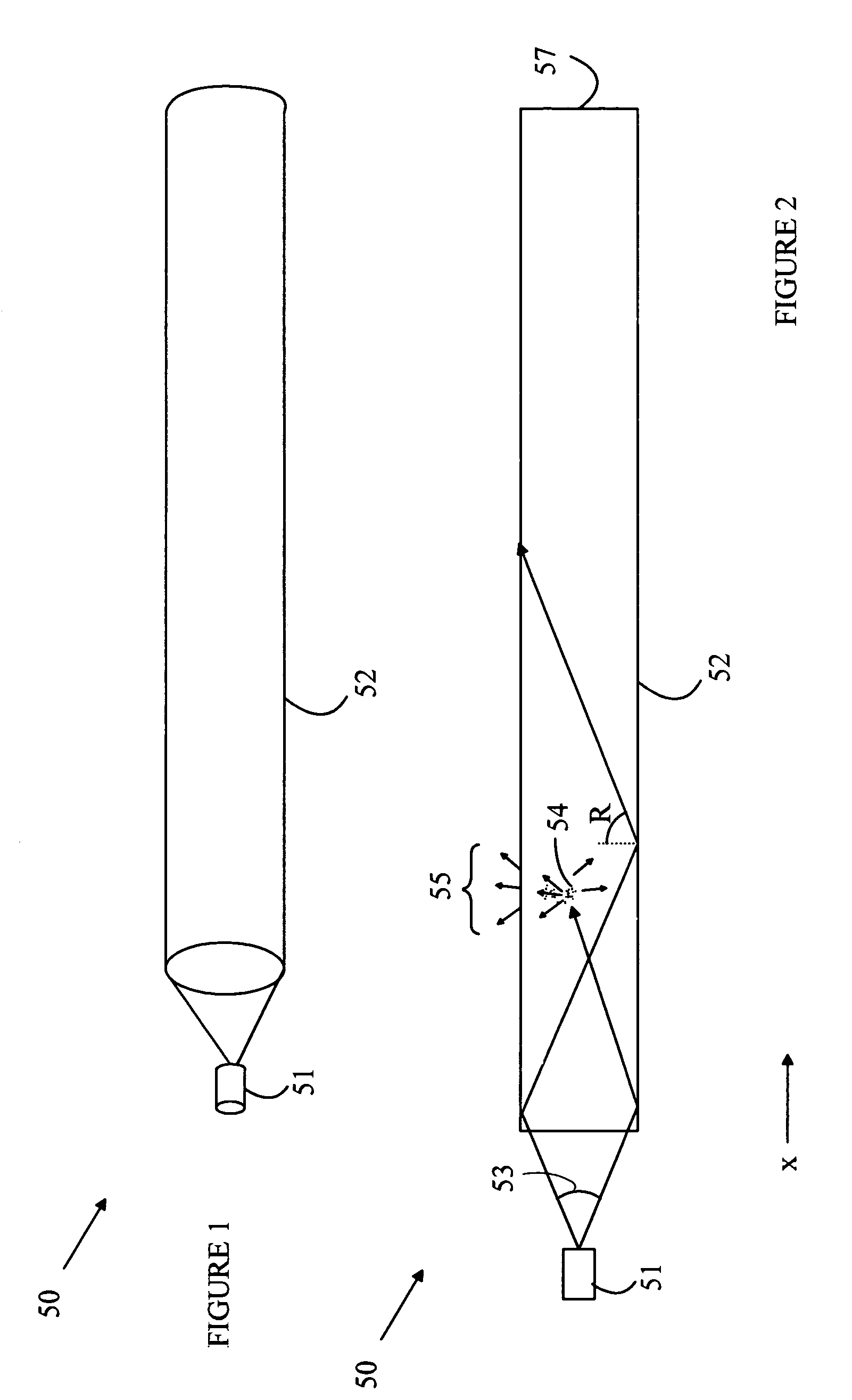
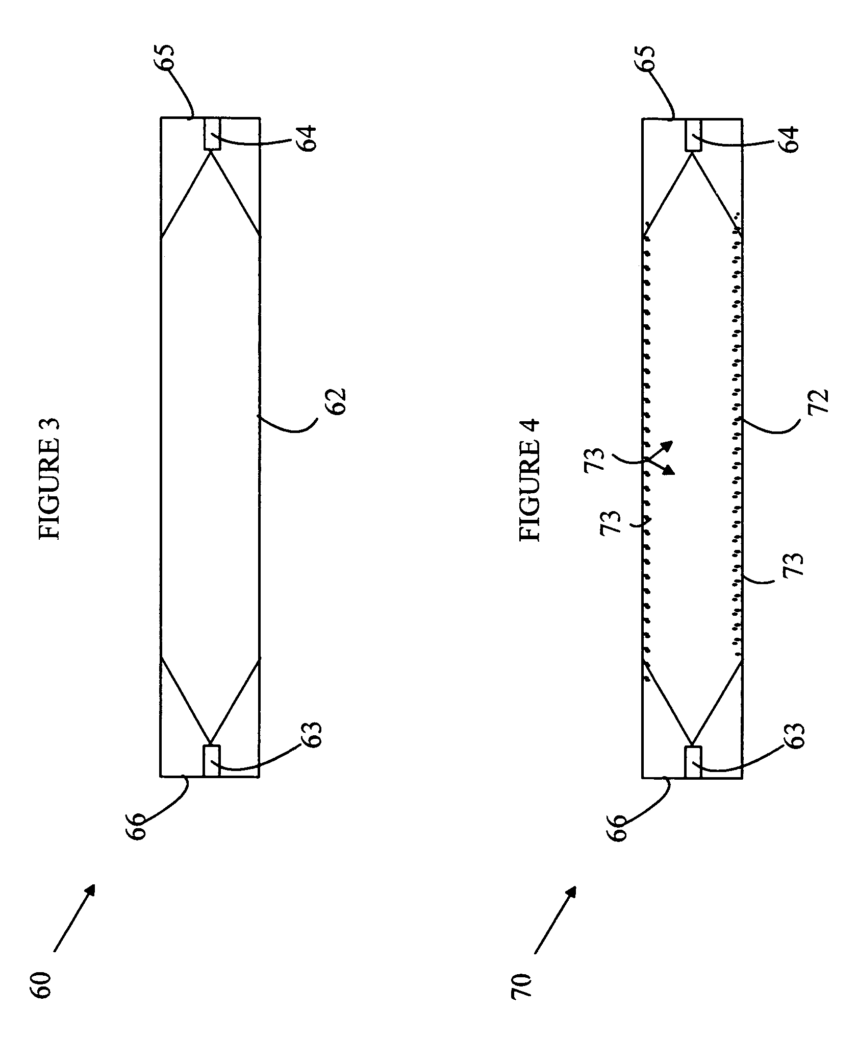
[0014]For the purposes of this discussion, the term “tube” is defined to be the volume swept out by a planar area that is moved along a center curve such that the planar area is perpendicular to the center curve. The planar area is characterized by a boundary curve that defines the edge of the planar area in the plane and by a maximum cross-sectional dimension, which is the maximum distance between two points on the boundary curve. The tube is characterized by a side tube surface and optionally two end surfaces. The side tube surface is defined to be the locus of points swept out by the boundary curve as the planar area moves perpendicular to the curve. It should be noted that the planar area could vary as a function of position along the center curve. In general, the length of the tube, i.e., the maximum distance along the curve between two points on the curve, is at least 10 times the maximum cross-sectional dimension.

[0015]The manner in which the present invention provides its ad...


PUM


Abstract

A tubular light source having a semiconductor light source and a tube is disclosed. The tube includes a transparent medium, the tube having a side tube surface, a center curve, one end surface, a length, and a maximum cross-sectional dimension. The tube includes scattering centers that cause light traveling in the tube to be reflected at angles such that the reflected light leaves the tube through the side tube surface. The semiconductor light source is positioned to emit light into the tube within a cone of angles such that the light will not leave the side tube surface in the absence of the scattering centers. The scattering centers can be dispersed in the transparent medium or located on the side tube surface. The transparent medium can be rigid or flexible.

Description

BACKGROUND OF THE INVENTION[0001]Advances in light-emitting diodes (LEDs) have made light sources constructed from such devices attractive alternatives to conventional light sources such as fluorescent lights and incandescent lights. LED-based light sources have energy conversion efficiencies approaching or exceeding those of these conventional light sources. In addition, the LED-based light sources have lifetimes that far exceed those of these conventional light sources. For example, a fluorescent light source has a lifetime of about 10,000 hours whereas an LED has a lifetime of 100,000 hours. In addition, fluorescent light sources tend to fail completely without warning. In contrast, LED-based light sources tend to fade over time or shift in color, and hence, the user has adequate warning so that the light source can be replaced before it completely fails.[0002]Fluorescent light sources are typically constructed from a glass tube containing a gas such as mercury vapor. The gas emi...

Claims


Application Information

Patent Timeline
Patent Type & Authority Patents(United States)
IPC IPC(8): H01L33/00F21K99/00
CPCF21K9/00G02B6/0003G02B6/001F21K9/27F21K9/64F21Y2115/10F21Y2113/13F21K9/69
Inventor NG, KEE YEANLEE, SIAN TATT
Owner DOCUMENT SECURITY SYST
Why Eureka
Try Eureka