Gas turbine having a sealing structure

a technology of sealing structure and gas turbine, which is applied in the field of gas turbines, can solve the problems of sealing plate assembly b, wear or damage, and increase maintenance costs, and achieve the effect of reducing the replacement frequency of sealing plate assemblies

Active Publication Date: 2009-06-23
MITSUBISHI POWER LTD
View PDF12 Cites 31 Cited by
  • Summary
  • Abstract
  • Description
  • Claims
  • Application Information

AI Technical Summary

Benefits of technology

[0015]It is an object of the present invention to solve such problems as described hereinabove, aiming at reducing the replacement frequency of sealing plate assemblies and providing a gas turbine which can have sealing plate assemblies thereof replaced easily at the site.

Problems solved by technology

As a result, there arises a problem that the sealing plate assemblies 71 will get worn or damaged in course of time, which requires a periodical replacement.
As a result, costs of a periodical overhaul inspection increase and a unit outage period becomes longer, which causes a problem that maintenance costs will further increase.

Method used


Image

  • Gas turbine having a sealing structure
  • Gas turbine having a sealing structure
  • Gas turbine having a sealing structure

Examples


Embodiment Construction

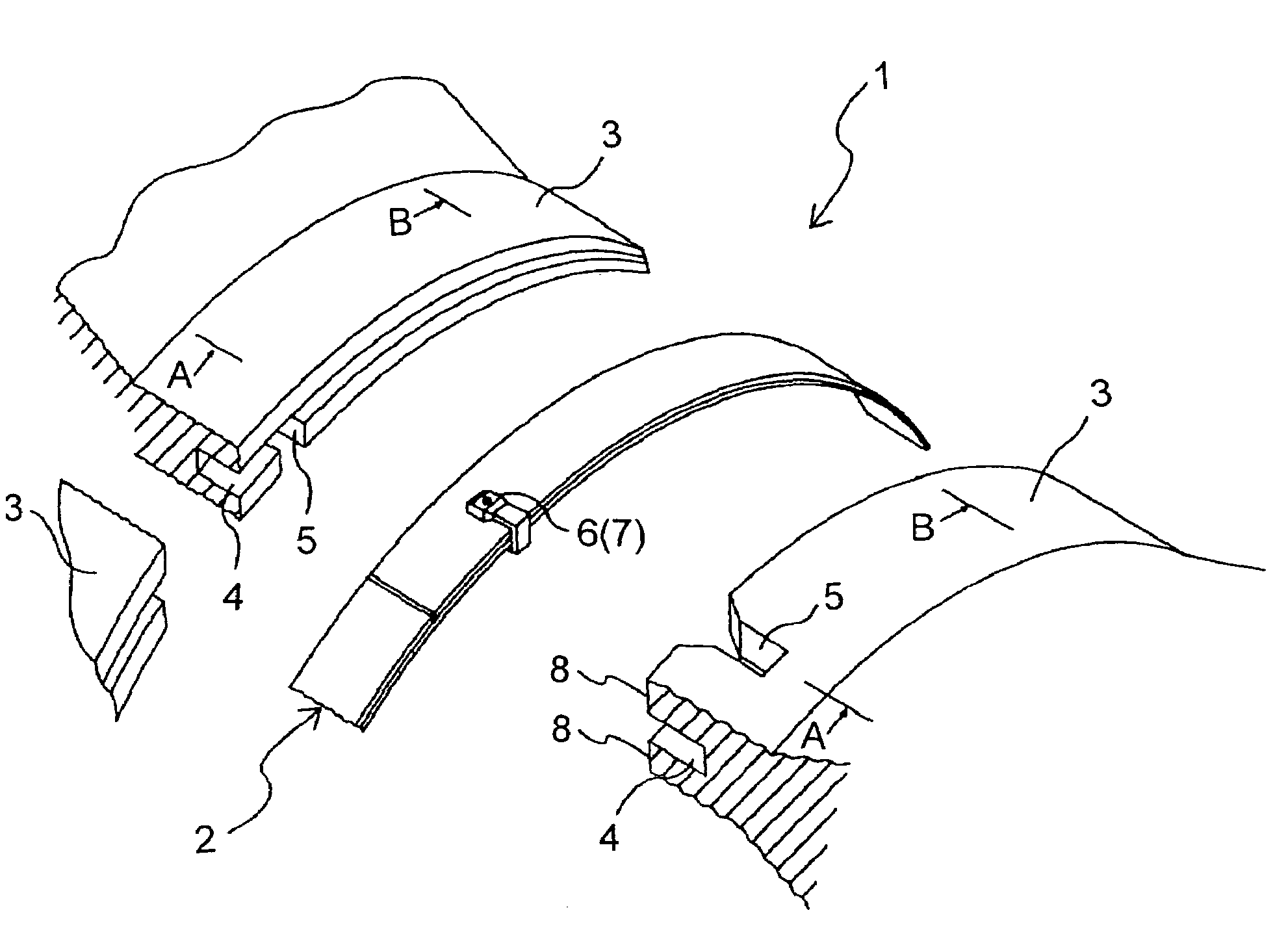
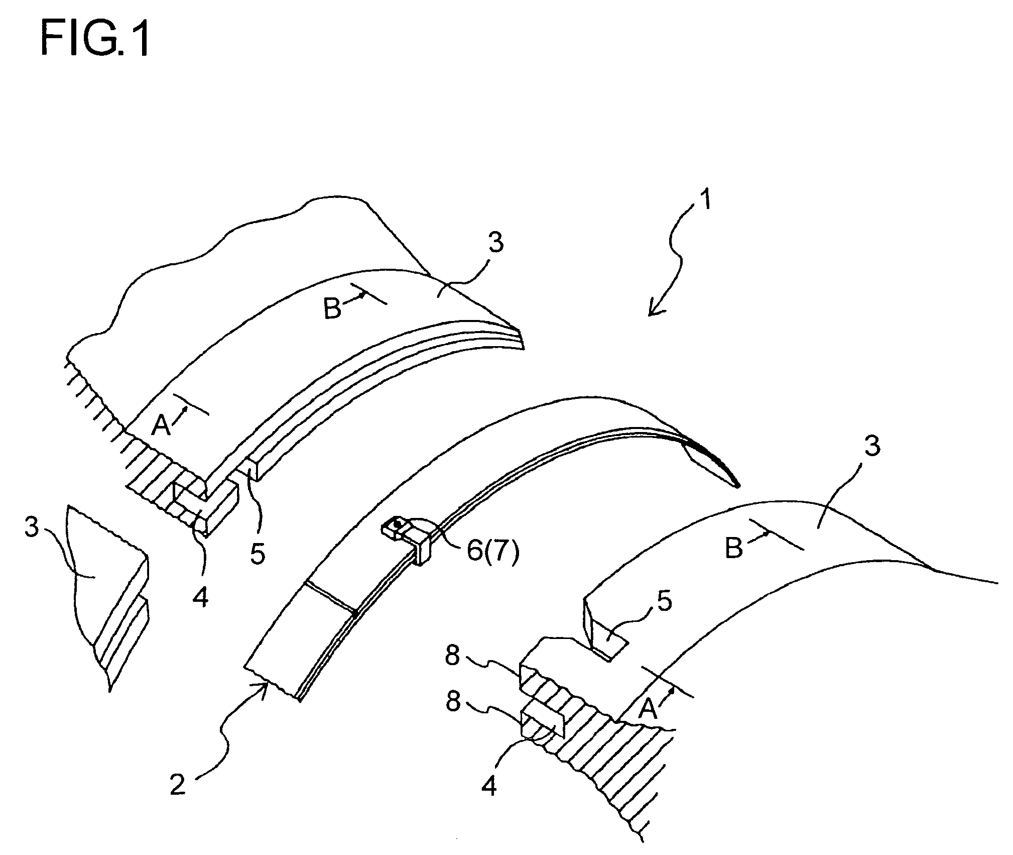
[0039]Referring now to the drawings, embodiments of the present invention will be described hereinafter. The following embodiments are examples of the present invention and not limited to. A sealing structure of a gas turbine in accordance with the present invention comprises overhang portions being provided to rotor discs; groove portions being provided to the overhang portions, a sealing plate assembly being inserted into the groove portions, and retaining members; wherein, a sealing plate assembly consists of an outside sealing plate and an inside sealing plate.

[0040]In addition, the construction of the gas turbine in accordance with the present invention and the structure of the rotor discs are the same as the conventional examples that are shown in FIG. 8 through FIG. 10. Therefore, same symbols will be applied to the same portions as in FIG. 8 through FIG. 10 and the detailed description thereof will be omitted.

[0041]FIG. 1 is a perspective view showing a sealing structure of ...


PUM


Abstract

In a gas turbine, annular overhang portions are formed on adjacent surfaces of a plurality of rotor discs so as to face each other, surrounding the rotor axis, groove portions are provided circumferentially to the surfaces of the overhang portions facing each other, and sealing structures are annularly installed to the inside of the groove portions. The gas turbine comprises sealing plate assemblies which include the overhang portions, the groove portions and a plurality of plates being formed annularly by being mutually piled up; and detachable retaining members which are provided so as to fix the overhang portions and the sealing plate assemblies together by way of disc engagement portions provided to the overhang portions and sealing plate engagement portions provided to the sealing plate assemblies.

Description

[0001]The present invention is based on Japanese Patent Application No. 2005-030170 filed on Feb. 7, 2005.BACKGROUND OF THE INVENTION[0002]1. Field of the Invention[0003]The present invention relates to a gas turbine being provided with a sealing structure preventing combustion gas or a cooling medium from leaking between rotor discs of the gas turbine.[0004]2. Description of the Prior Art[0005]A general construction of a gas turbine is shown in FIG. 8. The gas turbine compresses air in a compressor 51 and subsequently introduces the compressed air to a combustor 52. The combustor 52 generates combustion gas by supplying fuels to the compressed air and introduces the generated combustion gas to a turbine 53. The turbine 53 rotates by the combustion gas, and electric power is produced from a generator 54.[0006]In order to enhance the efficiency of a gas turbine, it is necessary to generate higher temperature combustion gas. Therefore, a cooling medium such as a cooling air or a cooli...

Claims


Application Information

Patent Timeline
Patent Type & Authority Patents(United States)
IPC IPC(8): F01D5/06
CPCF01D11/005F01D11/008F01D11/00F01D11/08F02C7/28
Inventor UWAMI, TAKUYACHIKAMI, RINTARO
Owner MITSUBISHI POWER LTD
Why Eureka
Try Eureka