X-ray inspection based on scatter detection

a scatter detection and x-ray technology, applied in the field of inspection systems, can solve the problems of inability to detect scatter, and inability to use detectors in applications requiring distances greater than five feet, so as to prevent damage to detectors and minimize bounce

Active Publication Date: 2009-06-23
AMERICAN SCI & ENG INC
View PDF75 Cites 112 Cited by
  • Summary
  • Abstract
  • Description
  • Claims
  • Application Information

AI Technical Summary

Benefits of technology

[0024]In accordance with further embodiments of the present invention, the source of penetrating radiation, the detector, or both may be located on one or more vehicles, including robotic drone vehicles, capable of road travel. The source of penetrating radiation may be mounted on a swivel mount to allow the beam to be directed at objects in various locations. The inspection system may further include a stabilization system to minimize bounce when the vehicle is traversing rough terrain.
[0025]In yet further embodiments of the present invention, the detectors may be located in the ground or ceiling of a passageway and may be camouflaged. Detectors located in the ground may further include structural supports to prevent damage to the detector when objects pass over, and pressure sensors to detect the presence of an object.

Problems solved by technology

One such application is where personnel to be inspected might be carrying explosive devices carried under clothing or concealed in backpacks or bags and the risk of suicide detonation is present.
Current x-ray inspection systems are often inadequate in such applications and are rarely used in applications requiring distances greater than five feet.
However, if the distances are too great, the detectors required will be impractically large.
Additionally, as the flux increases, so will the objects exposure, which poses a problem when the object is, or may contain, a person.
One consideration, however, is that metal objects (such as artillery shells) within a metallic container (such as a vehicle) may not be well-detected unless favorably silhouetted against a brightly scattering background of organic material.
Another issue for backscatter technology is that it can sometimes be difficult to image organic materials when they are placed within or behind significant amounts of high-Z material, such as steel.
This problem is often exacerbated because the scattered x-rays reach backscatter detectors having passed through an intervening steel surface at an oblique angle, resulting in an effective thickness of steel that is greater than the actual gauge of the steel.

Method used


Image

  • X-ray inspection based on scatter detection
  • X-ray inspection based on scatter detection
  • X-ray inspection based on scatter detection

Examples


Embodiment Construction

Distant Detection of Backscatter

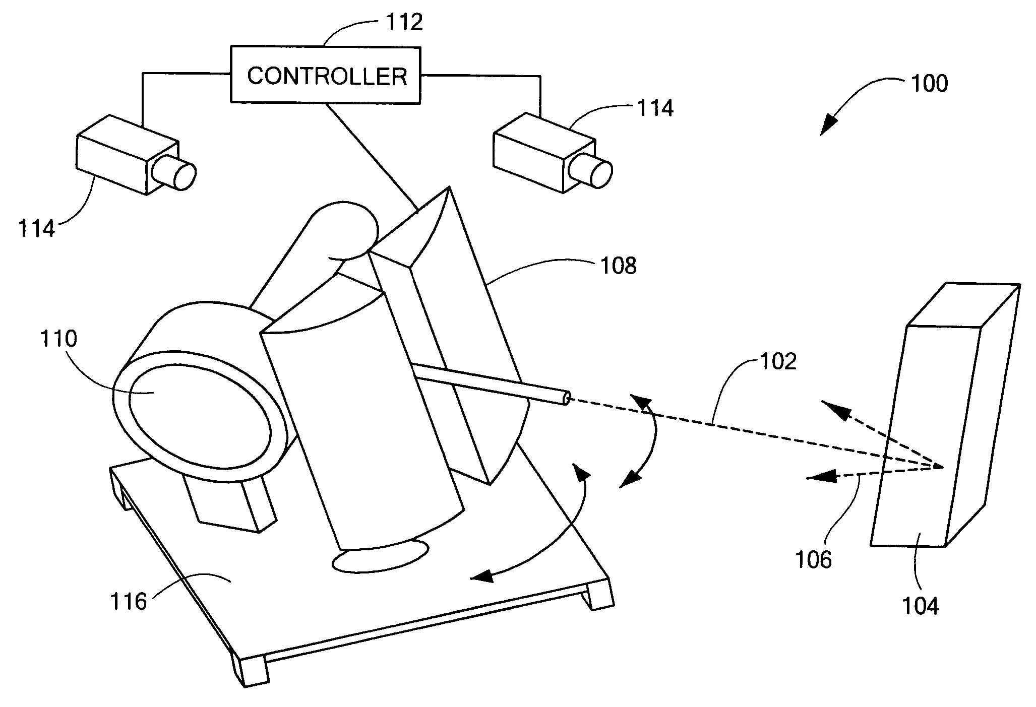
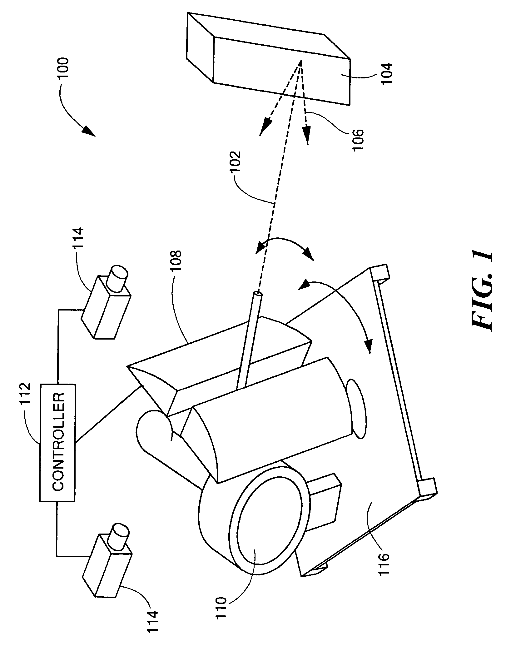
[0050]Embodiments of the present invention (which may be referred to as “Z-Radar”™) are now described with reference to FIG. 1. A backscatter inspection system, designated generally by numeral 100, use a collimated beam 102 of penetrating radiation, such as x-rays, to illuminate an object 104 (which, as indicated above, may include a person) at relatively large distances, to determine, for example, the metallic content on or within the object. An object will be said to be disposed at a “large distance” if the object of inspection, or a relevant portion thereof, subtends an angle of less than 5° in any direction as viewed from the source of illumination. Penetrating radiation may also include, for example, waves in other portions of the electromagnetic spectrum, such as gamma rays, but will be referred to, herein, as x-rays, without intended loss of generality. When the penetrating radiation is comprised of x-rays, the x-rays may be generated by an x-r...


PUM

PropertyMeasurementUnit
distancesaaaaaaaaaa
average energyaaaaaaaaaa
angleaaaaaaaaaa

Abstract

Systems and methods for inspecting an object with a scanned beam of penetrating radiation are disclosed. Scattered radiation from the beam is detected, in either the backward or forward direction. Characteristic values of the backscattered radiation are compared to expected reference values to characterize the object. Additionally, penetrating radiation transmitted through the inspected object may be combined with scatter information. In certain embodiments, the inspected field of view is less than 0.1 steradians, and the detector is separate from the source of penetrating radiation and is disposed, with respect to the object, such as to subtend greater than 0.5 steradians in the field of view of the object.

Description

[0001]The present application claims priority from three U.S. Provisional Patent Applications, Ser. Nos. 60 / 729,528 (filed Oct. 24, 2005), 60 / 729,548 (filed Oct. 24, 2005), and 60 / 748,909 (filed Dec. 9, 2005), all three of which applications are incorporated herein by reference.FIELD OF THE INVENTION[0002]The invention generally relates to inspection systems based upon remote detection of penetrating radiation scattered by an inspected object.BACKGROUND ART[0003]X-ray scattering may be employed for inspection of personnel, vehicles, cargo, or other objects of interest. The term “object” is used inclusively herein to encompass any of the above. In systems employing x-ray scattering, x-rays are formed into a beam that is directed towards the object of interest. When the beam hits the object, scattered X-rays are captured by x-ray detectors and various characteristics of the scattering object may be ascertained, either globally, or with respect to a pixelated image of the object.[0004]...

Claims


Application Information

Patent Timeline
Patent Type & Authority Patents(United States)
IPC IPC(8): G01N23/04
CPCG01N23/04G01N23/203G01V5/0016G01V5/0025
Inventor ROTHSCHILD, PETERSCHUBERT, JEFFREYBAUKUS, WILLIAM J.SAPP, JR., WILLIAM WADESCHUELLER, RICHARDCALLERAME, JOSEPHCASON, WILLIAM RANDALL
Owner AMERICAN SCI & ENG INC
Why Eureka
Try Eureka