Noise reduction apparatus and audio output apparatus

a technology of noise reduction and audio output, which is applied in the direction of broadcast circuit arrangement, broadcast system receiving, broadcast with distribution, etc., can solve the problems of large error and noise of correction error, and achieve the effect of reducing correction error and increasing noise suppression ability

Inactive Publication Date: 2009-06-23
MITSUBISHI ELECTRIC CORP
View PDF19 Cites 16 Cited by
  • Summary
  • Abstract
  • Description
  • Claims
  • Application Information

AI Technical Summary

Benefits of technology

[0016]In view of this point, the object of the present invention is to obtain a noise reduction apparatus by which the correction error can be reduced even for the signal in which many high frequency components are included, and the noise suppression ability is increased.

Problems solved by technology

Incidentally, in this method, the following problem exists.
That is, it is found that the relative relationship of the time width of the frequency to the correction period is very important, and even when a signal of a high frequency component is corrected, the error is large.
Accordingly, even when the correction is conducted on the signal of the high frequency component, the correction error is heard as a noise.

Method used


Image

  • Noise reduction apparatus and audio output apparatus
  • Noise reduction apparatus and audio output apparatus
  • Noise reduction apparatus and audio output apparatus

Examples


embodiment 1

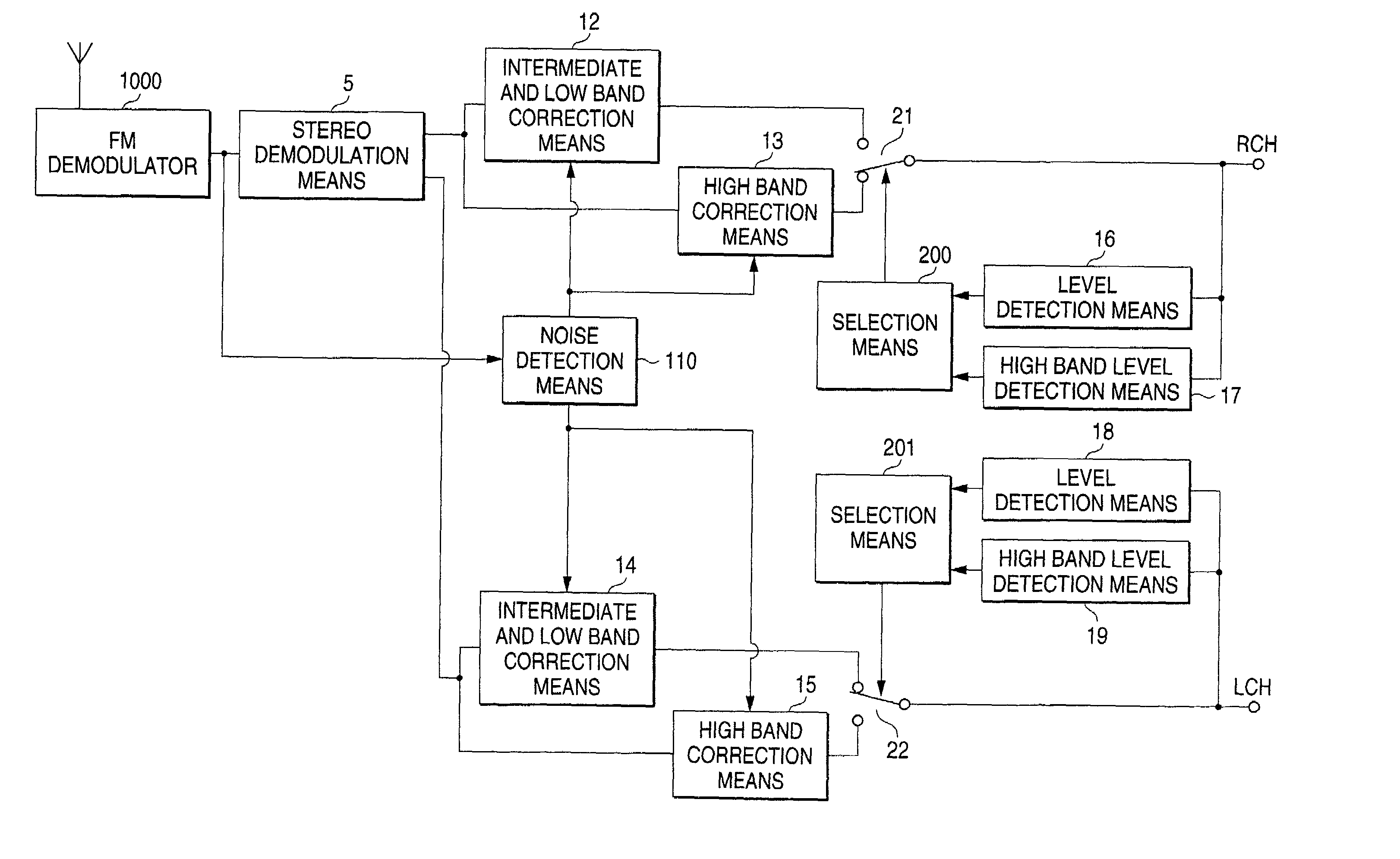
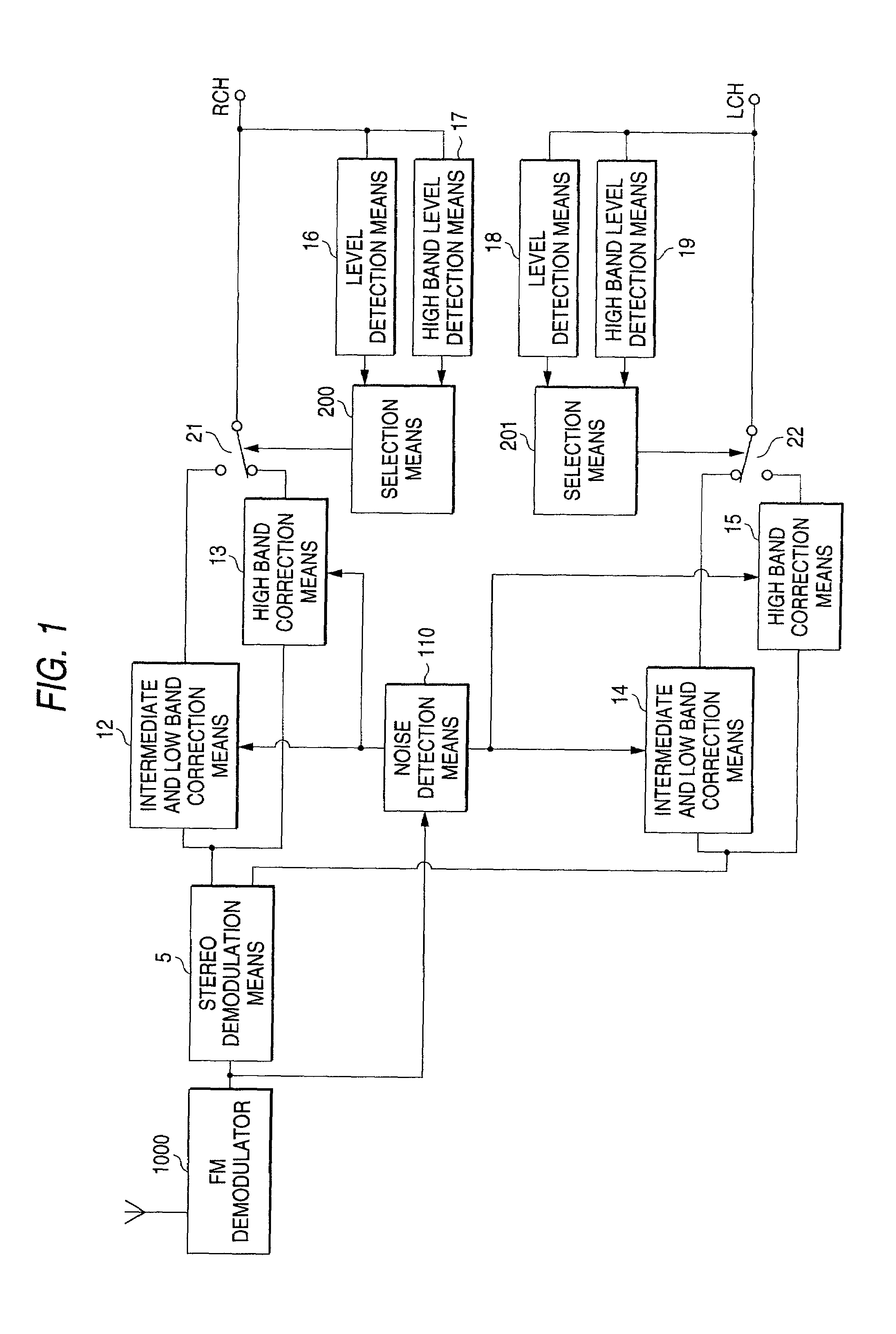
[0051]FIG. 1 is a block structural diagram of a noise reduction apparatus of the embodiment 1 of the present invention.

[0052]Numeral 1000 is an FM demodulation means for demodulating an FM signal from a received broadcasting wave, numeral 5 is a stereo demodulation means, numeral 12 is an intermediate and low band correction means for intermediate and low band signals of an Rch of the stereo demodulation means 5, numeral 13 is a high band correction means for a high band signal of the Rch of the stereo demodulation means 5, numeral 21 is a switch for switching output signals of the high band correction means 13 and intermediate and low band correction means 12, and numeral 14 is an intermediate and low band correction means for intermediate and low band signals of an Lch of the stereo demodulation means 5 (herein, the intermediate and low band correction means 12 and 14 are the first correction means provided respectively corresponding to the Rch and Lch).

[0053]Numeral 15 is a high ...

embodiment 2

[0091]FIG. 4 is a block structural diagram of the noise reduction apparatus of the embodiment 2 of the present invention. Numeral 5 is a stereo demodulation means, numeral 12 is an intermediate and low band correction means for conduct the correction on the intermediate and low band signal of the Rch of the stereo demodulation means 5, and numeral 13 is a high band correction means for conduct the correction on the high band signal of the Rch of the stereo demodulation means 5.

[0092]Numeral 21 is a switch to switch the output signals of the high band correction means 13 and intermediate and low band correction means 12, numeral 14 is an intermediate and low band correction means for an intermediate and low band signal of the Lch of the stereo demodulation means 5, and numeral 15 is a high band correction means for a high band signal of the Lch of the stereo demodulation means 5.

[0093]Numeral 22 is a switch to switch the output signals of the high band correction means 15 and interme...

embodiment 3

[0107]FIG. 7 is a block structural diagram of the noise reduction apparatus of the embodiment 3 of the present invention. In the drawing, numeral 112 is a noise detection means for detecting the pulsive noise from the output of the FM detection circuit 1, numeral 120 is an intermediate and low band correction means for conducting the correction on the intermediate and low band signals when there are many intermediate and low band components, in the output signals of the FM detection circuit 1, numeral 130 is a high band correction means for conducting the correction on the high band signals when there are many high band components, in the output signals of the FM detection circuit 1, and numeral 21 is a switch to switch the outputs of the intermediate and low band correction means 120 and the high band correction means 130.

[0108]Numeral 5 is a stereo demodulation means connected to the output signal of the switch 21, numeral 160 is a level detection means for detecting the level of ...


PUM

PropertyMeasurementUnit
frequencyaaaaaaaaaa
frequencyaaaaaaaaaa
frequencyaaaaaaaaaa

Abstract

The FM broadcast is received and the FM demodulated FM composite signal is stereo demodulated, and when the high band components of the demodulated signal are few, the correction is conducted by using the signals just before and just after the noise generation period, and when the high band components are large, the interpolation is conducted by using a central value calculated from the value of a predetermined period before the noise generation period, and a central value calculated from the value of a predetermined period after the noise generation period.

Description

BACKGROUND OF THE INVENTION[0001]The present invention relates to a noise reduction apparatus at the time of an audio signal receiving, and more specifically to a noise reduction apparatus used for, for example, a car radio in which a pulsive noise is easily mixed, and to an audio output apparatus.[0002]For example, when the electromagnetic noise in the circumstance of the car is considered, various pulsive electromagnetic noises (sometimes called the pulsive noise) such as an ignition noise, or mirror noise, are generated. Because these pulsive noises mix into a reception antenna connected to a car radio inside the car, it is ordinarily often experienced that the pulsive noise is generated in an output audio signal, therefore, generally for the car radio, the noise reduction apparatus to remove the pulsive noise is used.[0003]FIG. 8 is a block diagram of the conventional (pulsive) noise reduction apparatus disclosed in, for example, JP-A-63-87026. In the drawing, when an FM interme...

Claims


Application Information

Patent Timeline
Patent Type & Authority Patents(United States)
IPC IPC(8): H04B15/00G11B20/24H04B1/16
CPCG11B20/24H04B1/1661
Inventor TSUJISHITA, MASAHIROTSUJI, MASAYUKITAURA, KENICHIISHIDA, MASAYUKIASANO, EIZI
Owner MITSUBISHI ELECTRIC CORP
Why Eureka
Try Eureka