Boiler for making super heated steam and its use

a boiler and super heat technology, applied in the direction of steam generation using hot heat carriers, fire-box steam boilers, lighting and heating apparatus, etc., can solve the problems of mechanical failure of pipes, negative affecting the production of super heat steam,

Active Publication Date: 2009-06-30
SHELL USA INC
View PDF22 Cites 29 Cited by
  • Summary
  • Abstract
  • Description
  • Claims
  • Application Information

AI Technical Summary

Benefits of technology

[0005]The present invention provides a boiler, which makes use of the effective heat transfer resultant from the annular space design of the boiler of U.S. Pat. No. 3,867,907 but at the same time avoids some of the disadvantages of said design.
[0009]In the boiler of the present invention, saturated steam may flow co-currently with the hot gas or counter-currently with the hot gas through the annular space. In a co-current embodiment, the inlet is placed in the water bath space. In a counter-current embodiment, the outlet is placed in the water bath space. By positioning respective inlet and outlet in the water bath space, local overheating of the walls of the spirally conduit is avoided.

Problems solved by technology

A disadvantage of said design is that liquid water may enter the annular space, which will negatively affect the production of super heated steam.
Another disadvantage is that local overheating at the inlet of the annular space may occur which will give rise to mechanical failure of the pipes.

Method used


Image

  • Boiler for making super heated steam and its use
  • Boiler for making super heated steam and its use
  • Boiler for making super heated steam and its use

Examples


Embodiment Construction

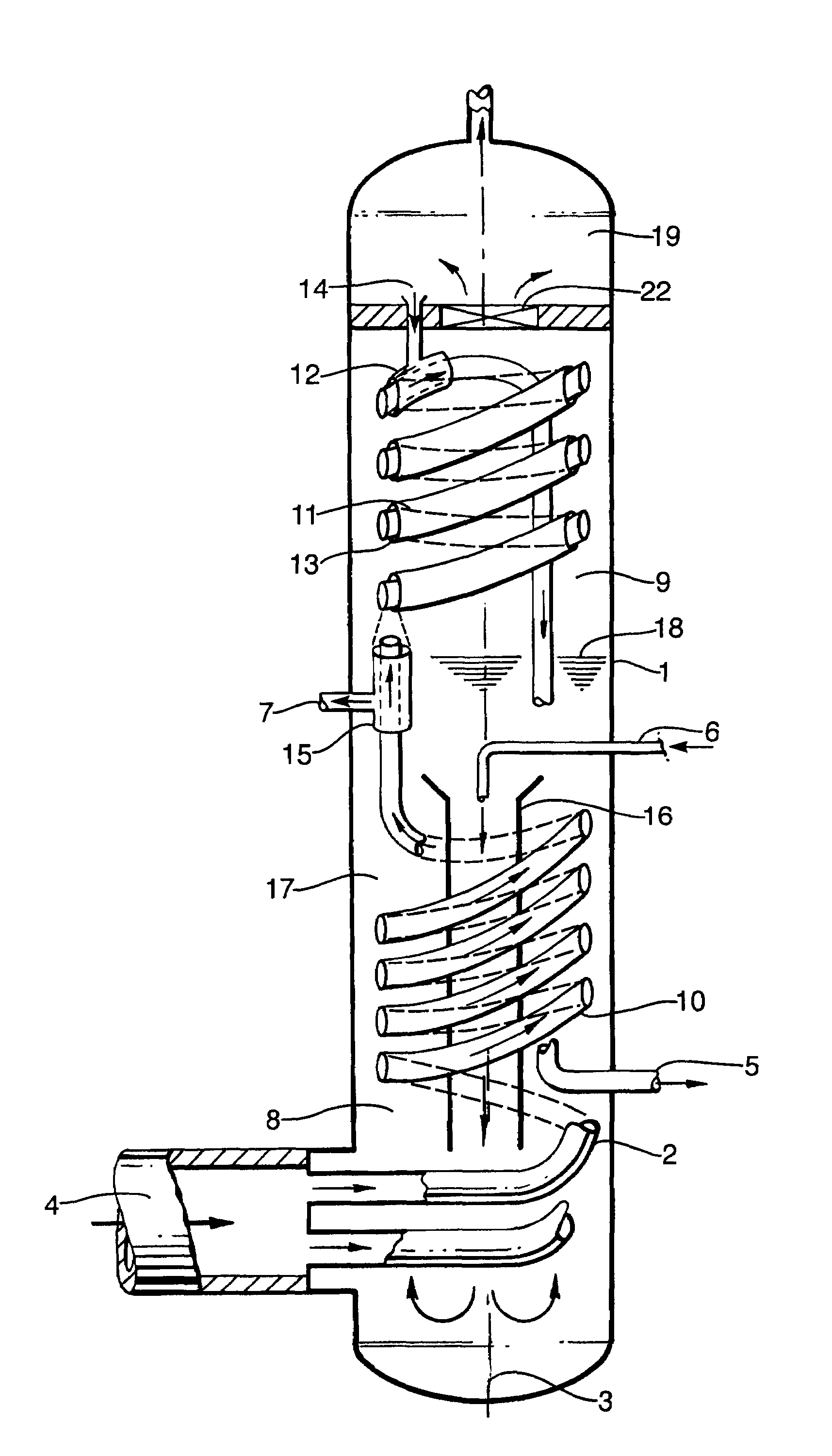
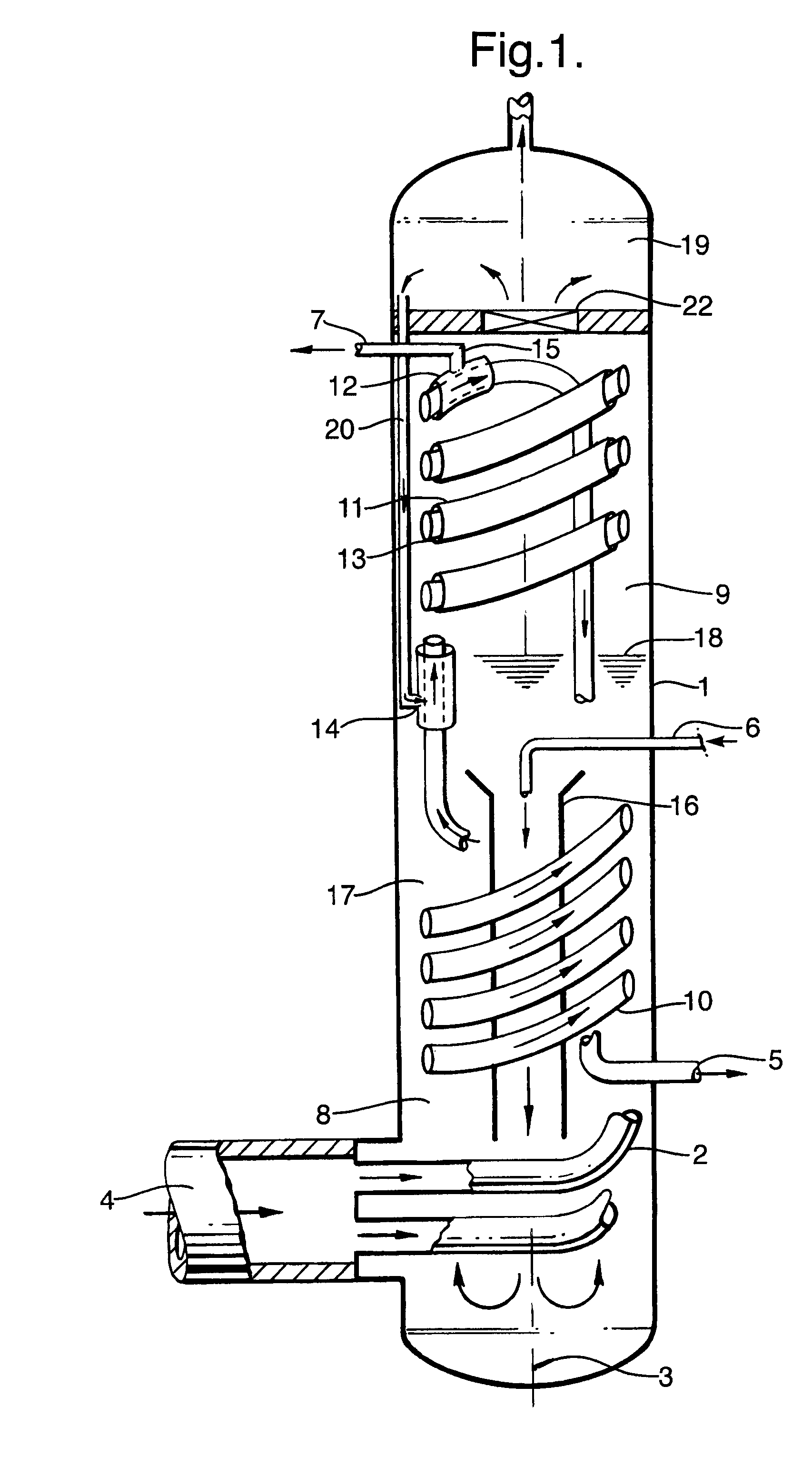
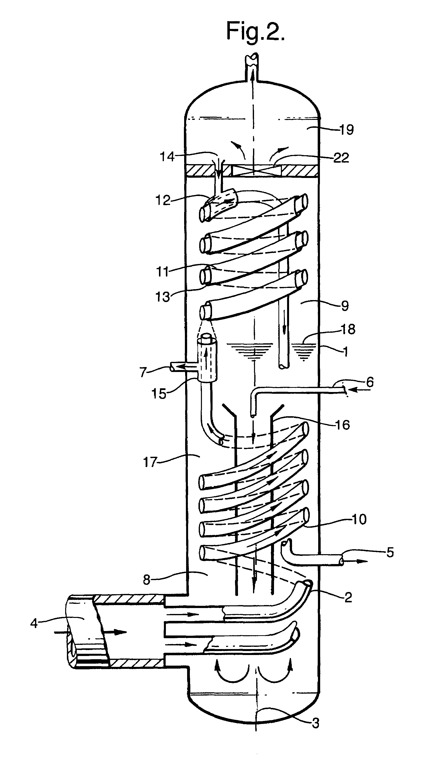
[0015]FIG. 1 illustrates a vertically oriented vessel 1 comprising a spirally formed conduit 2 around the vertical axis 3. Vessel 1 is provided with an inlet 4 for hot gas fluidly connected to the lower end of the conduit 2 for upwardly passage of hot gas through the spirally formed conduit 2. In the drawing only one spirally formed conduit 2 is shown. Generally from 2 up to and including 24 conduits 2 may run parallel in a vessel 1. Even higher number of conduits 2 may run parallel in vessel 1 if enough space is available.

[0016]Vessel 1 is further provided with a water bath space 8 in the lower end of the vessel 1 and a saturated steam collection space 9 above said water bath space 8.

[0017]FIG. 1 also shows an outlet 5 for cooled gas fluidly connected to the upper end of the conduit 2. In FIG. 1 the outlet 5 is positioned in the lower end of the vessel 1 such that some additional cooling may take place when passing the water bath space 8. Obviously this outlet 5 may also be positio...


PUM


Abstract

A boiler for making super heated steam by indirect heat exchange of water against a hot gas, said boiler being a vertically oriented vessel comprising a spirally formed conduit around the vertical axis of the vessel, which vessel is provided with an inlet for hot gas fluidly connected to the lower end of the conduit for upwardly passage of hot gas through the spirally formed conduit, an outlet for cooled gas fluidly connected to the upper end of the conduit, an inlet for fresh water and a vessel outlet for super heated steam,said vessel further provided with a water bath space in the lower end of the vessel and a saturated steam collection space above said water bath space,said spirally formed conduit comprising of a spirally formed evaporating section located in the water bath space and a spirally formed super heater section at the upper end of the vessel, wherein the conduit of the super heater section is surrounded by a second conduit forming an annular space between said super heater conduit and said second conduit, said annular space being provided with an inlet for saturated steam fluidly connected to the saturated steam collection space and an outlet for super heated steam located at the opposite end of said annular space and fluidly connected to the vessel outlet for super heated steam, wherein outlet or inlet are positioned in water bath space.

Description

[0001]This application claims the benefit of European application number 06114023.2 filed May 16, 2006 which is incorporated herein by reference.FIELD OF THE INVENTION[0002]The invention is directed to a boiler for making super heated steam by indirect heat exchange of water against a hot gas, a configuration comprising said boiler and to a process to prepare super heated steam.BACKGROUND OF THE INVENTION[0003]A boiler for making super heated steam is described in U.S. Pat. No. 3,867,907. In this apparatus a hot synthesis gas flows through tubular pipes, which are located in a water bath located at the lower end of a vertically oriented vessel. In said lower end saturated steam is generated. In the upper end of the vessel a conduit having a larger diameter than the tubular pipes surrounds said tubular pipes thereby defining an annular space around said pipes. The lower end of said annular space is open to receive saturated steam, which flows co-current with the hot syngas to the upp...

Claims


Application Information

Patent Timeline
Patent Type & Authority Patents(United States)
IPC IPC(8): F22B1/02
CPCF22B1/1884F22G3/005F28D7/14F28D7/024F28D7/106F22G3/006F22B1/18F22B25/00F22G3/00F28D1/02
Inventor BRINKMANN, JUERGENLAU, TECKSOONTHUL, HANS CHRISTIAN
Owner SHELL USA INC
Why Eureka
Try Eureka