Self-energized downhole tool

a technology of setting device and downhole tool, which is applied in the direction of earth drilling and mining, fluid removal, borehole/well accessories, etc., can solve the problems of limited well conditions of each of these techniques for setting downhole tools and associated costs to implemen

Active Publication Date: 2009-06-30
BAKER HUGHES HLDG LLC
View PDF61 Cites 97 Cited by
  • Summary
  • Abstract
  • Description
  • Claims
  • Application Information

AI Technical Summary

Problems solved by technology

Each of these techniques for setting a downhole tool has limitations in certain well conditions and associated costs to implement.

Method used


Image

  • Self-energized downhole tool
  • Self-energized downhole tool
  • Self-energized downhole tool

Examples


Embodiment Construction

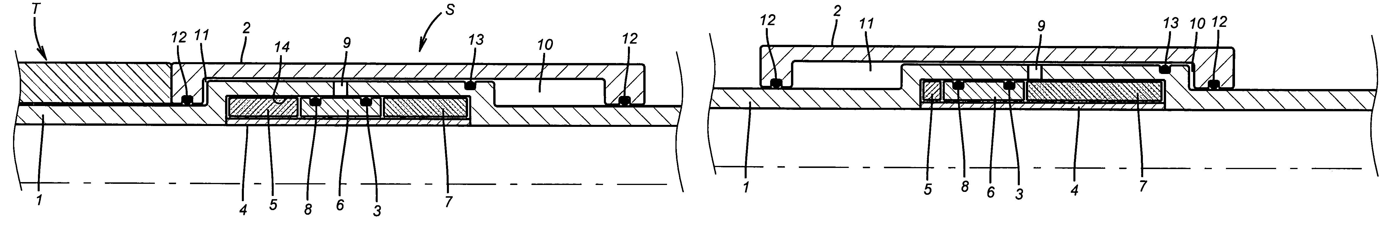
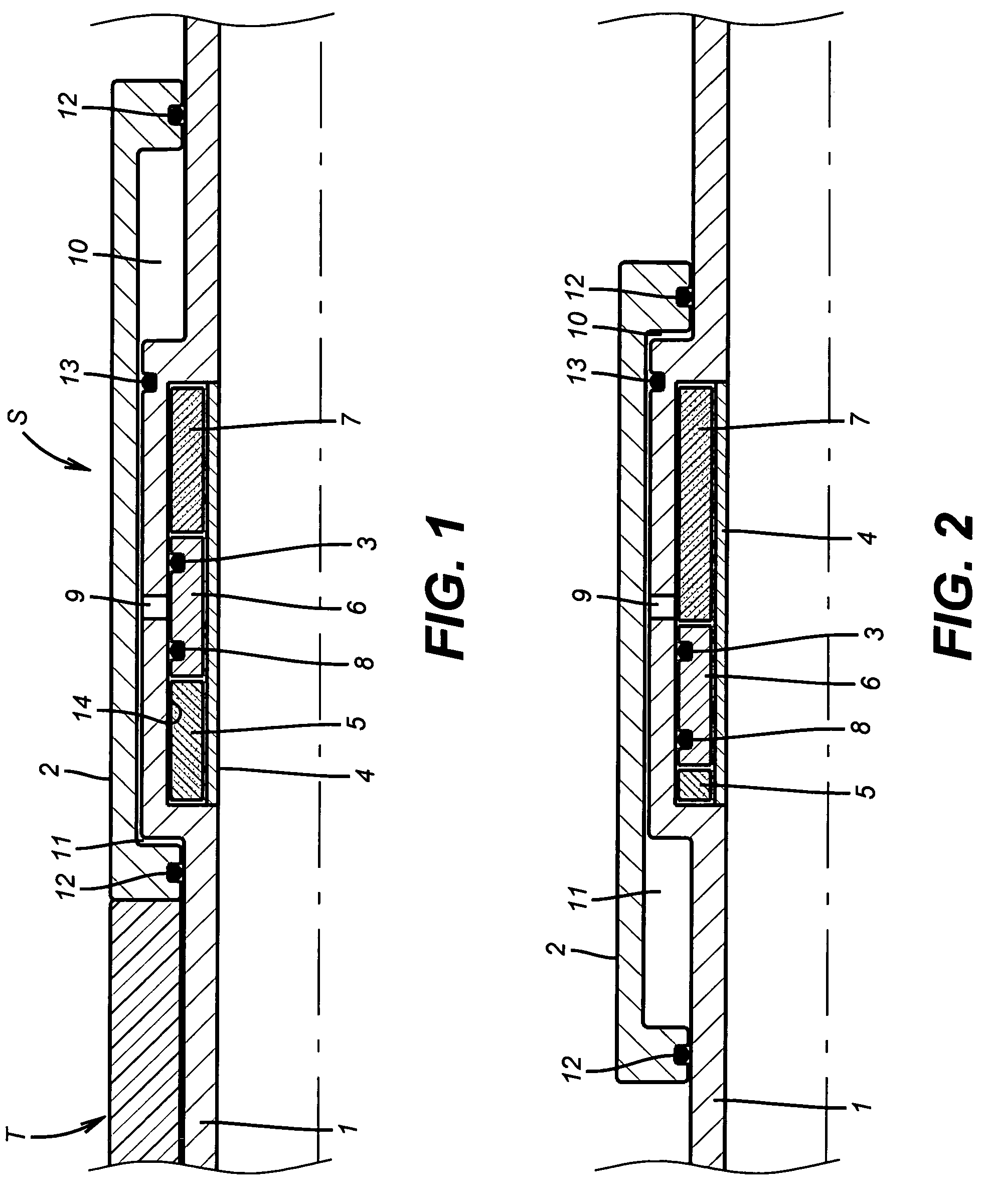
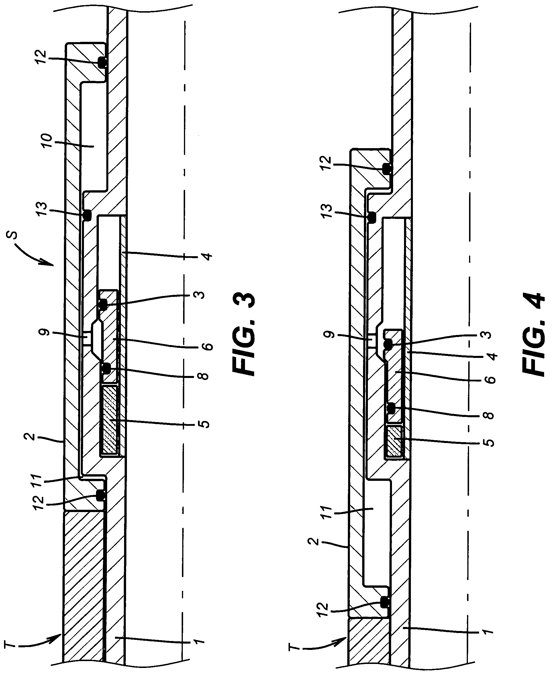
[0012]The mandrel 1 of the depicted setting tool S extends to a schematically illustrated downhole tool T that is preferably a packer but can be another type of tool known in the art. Mandrel 1 has a port 9 that is initially covered by a sleeve 6 that has seals 3 and 8 straddling the port 9 to keep it closed. Sleeve 6 is disposed in an internal recess 14 with a restrainer 5 on one side and an energy source 7 on the other side. Energy source 7 can't move the sleeve 6 as long as restrainer 5 is serviceable. A protective sleeve 4 overlays sleeve 6, energy source 7 and restrainer 5 to protect hem from tools or other objects moved through mandrel 1. Sleeve 4 allows well fluids in the mandrel 1 to get to restrainer 5 and energy source 7 as will be described below.

[0013]Piston 2 covers port 9 and is mounted to mandrel 1 with seals 12 located at or near opposed ends. Seal 13 seals between the mandrel 1 and the piston 2 in a way to define atmospheric chamber 10 near the end opposite from too...


PUM


Abstract

Setting mechanisms for downhole tools are described that take advantage of hydrostatic pressure in the wellbore which is harnessed to set a tool after exposure to well fluids for a given time or temperature defeats a lock and allows hydrostatic forces to trigger the setting of the tool. Alternatively, some other biasing source is released to set the downhole tool after exposure to well fluids for a time or a temperature and time defeats a lock and allows the biasing source to set the tool. While applications to packers are preferred, other downhole tools can be set in his manner removing the need for an inner string, dropping a ball on a seat or pressurizing the wellbore to achieve the setting of the downhole tool.

Description

FIELD OF THE INVENTION[0001]The field of this invention relates to setting devices for downhole tools that automatically actuate them after certain conditions are met and more particularly focuses on time or temperature or combinations of those conditions.BACKGROUND OF THE INVENTION[0002]Devices to actuate downhole tools such as external casing packers, for example normally require an inner string to shift a sliding sleeve or a straddle tool to bridge over an inflate port to set the downhole tool. Other techniques involve dropping a ball on a seat or pressurizing the wellbore. Each of these techniques for setting a downhole tool has limitations in certain well conditions and associated costs to implement.[0003]What is needed and made possible by the present invention is a technique to set a downhole tool in an alternative way based on conditions that exist in the wellbore. In a specific embodiment exposure to well fluids at a predetermined temperature for a predetermined time allows...

Claims


Application Information

Patent Timeline
Patent Type & Authority Patents(United States)
IPC IPC(8): E21B23/00
CPCE21B23/00E21B23/04E21B23/06E21B23/042
Inventor MURRAY, DOUGLAS J.BERZIN, VELWOOD, EDWARD T.BADKE, GREGORY C.
Owner BAKER HUGHES HLDG LLC
Why Eureka
Try Eureka