Preventing harmful polarization of solar cells

a solar cell and polarization technology, applied in the field of solar cells, can solve problems such as reducing output power

Active Publication Date: 2009-06-30
MAXEON SOLAR PTE LTD +1
View PDF14 Cites 125 Cited by
  • Summary
  • Abstract
  • Description
  • Claims
  • Application Information

AI Technical Summary

Benefits of technology

[0007]In one embodiment, harmful solar cell polarization is prevented or minimized by providing a conductive path that bleeds charge from a front side of a solar cell to the bulk of a wafer. The conductive path may include patterned holes in a dielectric passivation layer, a conductive anti-reflective coating, or layers of conductive material formed on the top or bottom surface of an anti-reflective coating, for example. Harmful solar cell polarization may also be prevented by biasing a region of a solar cell module on the front side of the solar cell.

Problems solved by technology

If precautions are not taken, solar cells may become highly polarized in the field, causing reduced output power.

Method used


Image

  • Preventing harmful polarization of solar cells
  • Preventing harmful polarization of solar cells
  • Preventing harmful polarization of solar cells

Examples


Embodiment Construction

[0016]In the present disclosure, numerous specific details are provided, such as examples of apparatus, components, and methods, to provide a thorough understanding of embodiments of the invention. Persons of ordinary skill in the art will recognize, however, that the invention can be practiced without one or more of the specific details. In other instances, well-known details are not shown or described to avoid obscuring aspects of the invention.

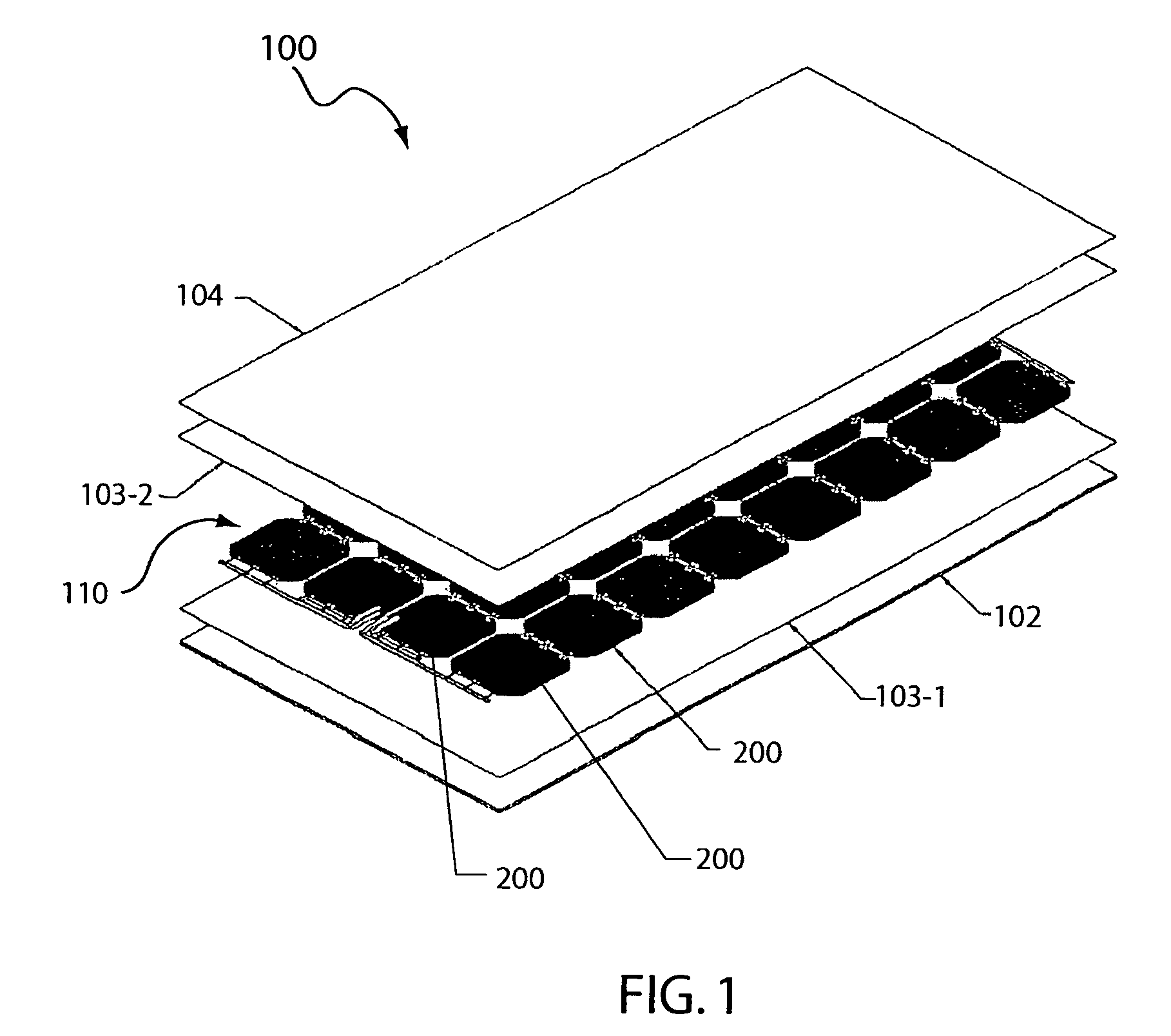
[0017]Referring now to FIG. 1, there is shown an exploded view of an example solar cell module 100 that may take advantage of embodiments of the present invention. Such a solar cell module is also disclosed in commonly-assigned U.S. application Ser. No. 10 / 633,188, filed on Aug. 1, 2003. It is to be noted, however, that embodiments of the present invention are also applicable to other solar cell modules.

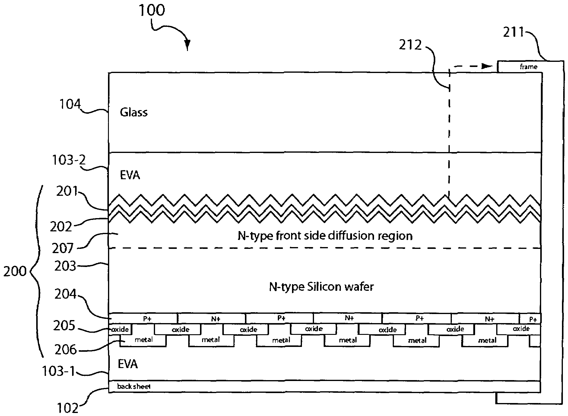
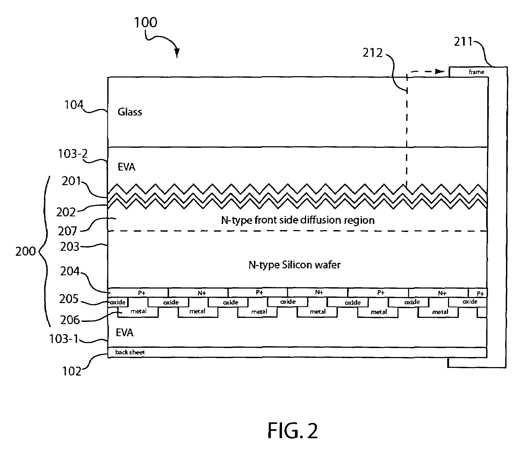
[0018]In the example of FIG. 1, the solar cell module 100 includes a transparent cover 104, encapsulants 103 (i.e., 103-1, 103-2), a solar ...


PUM

PropertyMeasurementUnit
thicknessaaaaaaaaaa
thicknessaaaaaaaaaa
thicknessaaaaaaaaaa

Abstract

In one embodiment, harmful solar cell polarization is prevented or minimized by providing a conductive path that bleeds charge from a front side of a solar cell to the bulk of a wafer. The conductive path may include patterned holes in a dielectric passivation layer, a conductive anti-reflective coating, or layers of conductive material formed on the top or bottom surface of an anti-reflective coating, for example. Harmful solar cell polarization may also be prevented by biasing a region of a solar cell module on the front side of the solar cell.

Description

CROSS-REFERENCE TO RELATED APPLICATION[0001]This application claims the benefit of U.S. Provisional Application No. 60 / 658,706, filed Mar. 3, 2005, which is incorporated herein by reference in its entirety.BACKGROUND OF THE INVENTION[0002]1. Field of the Invention[0003]The present invention relates generally to solar cells, and more particularly but not exclusively to solar cell structures, modules, fabrication, and field installation.[0004]2. Description of the Background Art[0005]Solar cells are well known devices for converting solar radiation to electrical energy. They may be fabricated on a semiconductor wafer using semiconductor processing technology. Generally speaking, a solar cell may be fabricated by forming p-type regions and n-type regions in a silicon substrate. Each adjacent p-type region and n-type region forms a p-n junction. Solar radiation impinging on the solar cell creates electrons and holes that migrate to the p-type and n-type regions, thereby creating voltage...

Claims


Application Information

Patent Timeline
Patent Type & Authority Patents(United States)
IPC IPC(8): H01L31/00
CPCH01L31/02167H01L31/02168H01L31/048H01L31/022466Y02E10/547Y02E10/52Y10T29/49117Y02B10/10Y02E10/56Y02E10/50H01L31/04H01L31/0216H01L31/042H02J3/38H02S40/32H01L31/0504H01L31/18H01L31/049H01L31/0516H02S30/10H02S40/36
Inventor SWANSON, RICHARD M.DE CEUSTER, DENISDESAI, VIKASROSE, DOUGLAS H.SMITH, DAVID D.KAMINAR, NEIL
Owner MAXEON SOLAR PTE LTD
Why Eureka
Try Eureka