Communication terminal and communication network

a terminal and terminal technology, applied in the field of communication networks, can solve the problems of single-path communication process, unstable single-path communication process, broken path, etc., and achieve the effect of effectively using network resources, avoiding radio interference, and stabilizing communication

Inactive Publication Date: 2009-06-30
OKI ELECTRIC IND CO LTD
View PDF9 Cites 12 Cited by
  • Summary
  • Abstract
  • Description
  • Claims
  • Application Information

AI Technical Summary

Benefits of technology

[0009]An object of the present invention is to provide communication terminals and communication networks that improve on conventional single-path and multipath routing schemes in order to stabilize communication, avoid radio interference, and effectively use network resources.
[0010]In one embodiment of the invention, each time a communication terminal receives a packet from a neighboring terminal, it stores the identifier (ID) of the neighboring terminal and the ID of the source terminal from which the data originated in association with each other in a routing control cache. The ID of the neighboring terminal is stored as a relay terminal ID; the ID of the source terminal is stored as a destination terminal ID. If the communication terminal already holds the ID of the destination terminal of the data in the routing control cache as a destination terminal ID, it also relays the data toward its destination through the neighboring relay terminal(s) associated with the destination terminal. This scheme enables multiple paths between two terminals to be established automatically, simply by having the two terminals flood the communication network with route request and reply messages, without requiring distance calculations or other complex processing.
[0011]In another embodiment of the invention, the routing control cache stores the IDs of associated pairs of endpoint terminals. A separate neighboring terminal ID storage unit is used to store the IDs of neighboring terminals from which the communication terminal receives data. If the source and destination terminals of the received data are associated as endpoint terminals in the routing control cache, the communication terminal routes the received data through the neighboring terminals listed in the neighboring terminal ID storage unit. When a source terminal wishes to communicate with a destination terminal, it selects a single path to the destination terminal, and sends a route request message to a terminal on the path. This terminal then sends route command messages to all terminals within a certain number of hops of itself. The route request message gives the IDs of the source and destination terminals as a pair of endpoint terminal IDs. The route command message instructs receiving terminals to put the endpoint terminal IDs in their routing control cache. This scheme enables a single path to be expanded to multiple paths without the need for complex processing.
[0013]Still another embodiment of the invention uses both a routing control cache listing destination terminal IDs and associated relay terminal IDs, and a hopcount cache. A communication terminal relays received data toward its destination terminal through the associated relay terminals provided the sum of the number of hops from the source terminal and the number of hops to the destination terminal does not exceed a ceiling given in the received data. This scheme enables routing to be restricted to the shortest path (or paths) between the source and destination terminals, and paths with total hopcounts not exceeding the hopcount of the shortest path by more than a specified quantity. Besides enabling multiple paths to be set up automatically by a simple procedure, this routing scheme allows the paths to diverge in all directions from the source and destination terminals, thereby avoiding path convergence around those terminals, providing greater path redundancy, and reducing interference.
[0014]The hopcount ceiling may be originally set to the hopcount of the shortest path and then raised if communication proves unstable. Paths may also be prioritized according to, for example, the difference between their total hopcount and the hopcount of the shortest path, and routing may be restricted to paths with certain priority values to further reduce path crowding and usage of network resources. Alternatively, data received on lower-priority paths may be suspended temporarily and relayed toward the destination terminal only if not routed on a higher-priority path within a given suspension time.

Problems solved by technology

The problem with single-path routing is that if a terminal on the single designated path drops out because, for example, its battery runs down, or because the terminal moves to another location, the path is broken and communication ceases.
The single-path communication process therefore tends to be unstable with frequent interruptions.
The plurality of communication paths reduces the likelihood of communication interruptions, because a failure on one path can generally be dealt with by immediately switching to another path, but the complex processing required to define the paths and make them available imposes a burden on the computational resources of the terminals.
An additional problem is that the multiple paths tend to converge near the source and destination terminals, reducing path redundancy in these areas and making radio interference a problem.
A further problem is that when communication is stable, multipath routing wastes network resources.
This further problem could be overcome by switching between single-path routing and multipath routing, but that would only increase the complexity of the routing control process.
Communication therefore tends to be unstable.
Although conventional multipath routing schemes can deal with such path breakdowns because they provide a plurality of communication paths, they also involve much control overhead: paths are selected through a complex computational process, and the paths have to be set up by an elaborate control process.
Conventional multipath routing therefore tends to squander network resources.

Method used


Image

  • Communication terminal and communication network
  • Communication terminal and communication network
  • Communication terminal and communication network

Examples


first embodiment

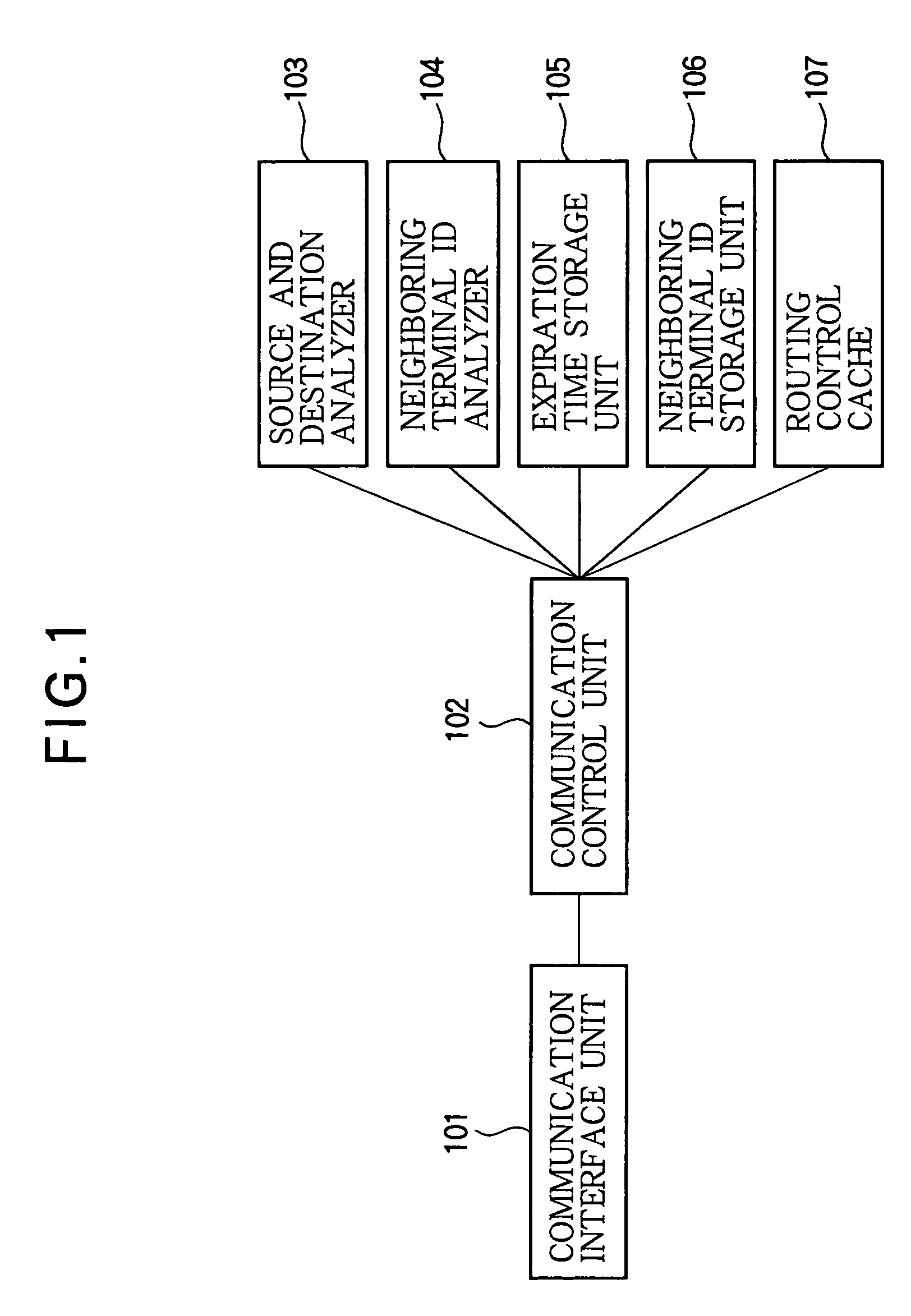
[0044]Referring to FIG. 1, each communication terminal in the first embodiment has a communication interface unit 101, a communication control unit 102, a source and destination analyzer 103, a neighboring terminal ID analyzer 104, an expiration time storage unit 105, a neighboring terminal ID storage unit 106, and a routing control cache 107, which are interconnected as shown. All of the elements shown in FIG. 1 may be implemented in hardware, but some of them may also be implemented partly or wholly in software executed on a general-purpose computing device such as a microprocessor.

[0045]The communication interface unit 101 interfaces with other communication terminals in the network.

[0046]The communication control unit 102 receives packets from the communication network via the communication interface unit 101, and sends packets to the communication network via the communication interface unit 101. The communication control unit 102 also sends received packets to the source and d...

second embodiment

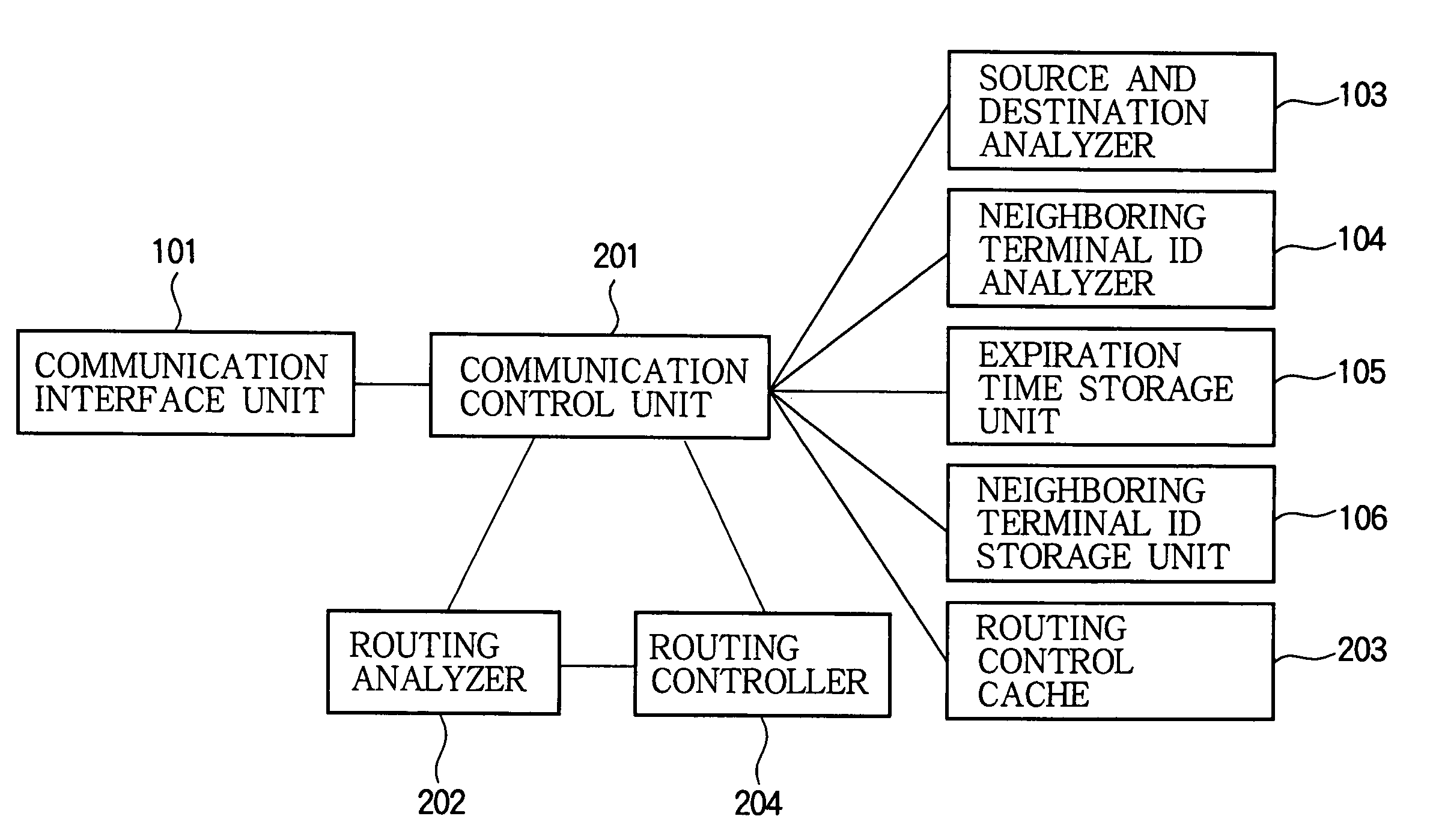
[0066]Referring to FIG. 7, the communication terminals in the second embodiment have a communication interface unit 101, a communication control unit 201, a source and destination analyzer 103, a routing analyzer 202, a neighboring terminal ID analyzer 104, an expiration time storage unit 105, a neighboring terminal ID storage unit 106, a routing control cache 203, and a routing controller 204, which are interconnected as shown.

[0067]The communication interface unit 101 interfaces with other communication terminals in the network.

[0068]The communication control unit 201 receives packets from the communication network and sends packets to the communication network via the communication interface unit 101. Among the packets sent to the communication network are route command message packets supplied by the routing controller 204.

[0069]The communication control unit 201 sends received packets to the source and destination analyzer 103, neighboring terminal ID analyzer 104, and routing ...

third embodiment

[0094]Referring to FIG. 13, the communication terminals in the third embodiment have a communication interface unit 101, a communication control unit 301, a source and destination analyzer 103, a neighboring terminal ID analyzer 104, an expiration time storage unit 105, a neighboring terminal ID storage unit 106, a hopcount controller 302, and a hopcount cache 303, which are interconnected as shown.

[0095]The communication interface unit 101 interfaces with other communication terminals in the network.

[0096]The communication control unit 301 receives packets from the communication network via the communication interface unit 101, and transmits packets to the communication network. The packets in the third embodiment include a pair of hopcount values indicating the number of hops from the source terminal and the number of hops to the destination terminal. Among the packets received from the network are route request message packets. The communication control unit 301 sends all receive...


PUM


Abstract

Routing schemes are provided for a communication network. In one scheme, destination terminals and associated neighboring terminals are listed in a routing control cache at each communication terminal in the network, and packets are routed toward the destination terminal through the associated neighboring terminals. In another scheme, a single path from a source terminal to a destination terminal is automatically expanded into multiple paths. In yet another scheme, packets are routed as long as this does not increase the number of hops to the destination terminal. These schemes enable multiple paths to be established by a simple procedure not requiring complex distance calculations. In still another scheme, routing is restricted to the shortest path and paths up to a given number of hops longer than the shortest path, permitting paths to diverge in multiple directions from the source and destination terminals.

Description

BACKGROUND OF THE INVENTION[0001]1. Field of the Invention[0002]The present invention relates to a communication network such as an ad hoc network comprising a plurality of communication terminals, to the terminals in the network, and in particular to the routing method employed in the network.[0003]2. Description of the Related Art[0004]Communication in an ad hoc network takes place by the routing of packets from a source terminal to a destination terminal on a path that may lead through one or more intermediate or relay terminals. All of the terminals in the network are capable of operating as routers, that is, of designating the paths or routes that packets will follow. The routing methods employed in an ad hoc network include both single-path and multipath schemes.[0005]Conventional single-path routing decreases the amount of usage of network resources by selecting a single path between the source terminal and the destination terminal and switching data on that path as described...

Claims


Application Information

Patent Timeline
Patent Type & Authority Patents(United States)
IPC IPC(8): H04L12/28H04L12/54H04L12/56
CPCH04L45/00H04L45/122H04L45/24
Inventor NAKAMURA, NOBUYUKIKADO, YOUITI
Owner OKI ELECTRIC IND CO LTD
Why Eureka
Try Eureka