Perpendicular magnetic recording write head with flux-conductor contacting write pole

a technology of flux-conductor and write pole, which is applied in the direction of magnetic recording heads, data recording, instruments, etc., can solve the problems of difficult precision control of flare angle and fabrication of flared write poles, and achieve the effect of wide tolerance and simplified manufacturing process

Inactive Publication Date: 2009-07-07
WESTERN DIGITAL TECH INC
View PDF9 Cites 32 Cited by
  • Summary
  • Abstract
  • Description
  • Claims
  • Application Information

AI Technical Summary

Benefits of technology

[0006]The invention is a perpendicular magnetic recording write head with a flux conductor in contact with the write pole. The flux conductor is substantially wider than the write pole tip in the cross-track direction and has a blunt or generally planar end that is recessed from the pole tip end. The flux conductor, which is in contact with the write pole above and below the flare point, acts as a flux shaping layer to carry some of the flux away from flare point. The region of the flux conductor where its blunt end is in contact with the pole tip is the “choke” point for the write pole, i.e., the point where the flux density is highest. The flux conductor enables the write pole to be made with no flare, or with a flare angle and throat height with a much wider tolerance, which substantially simplifies the manufacturing process. The write head may have a trailing shield and side shields that substantially surround the write pole tip and remove stray fields that may be produced by the flux conductor, so that regions of the recording layer other than the track being written are not adversely affected.

Problems solved by technology

The fabrication of the flared write pole, particularly the flare point location (which defines the “throat height” of the write pole tip) and the flare angle are difficult to control with precision during manufacturing.

Method used


Image

  • Perpendicular magnetic recording write head with flux-conductor contacting write pole
  • Perpendicular magnetic recording write head with flux-conductor contacting write pole
  • Perpendicular magnetic recording write head with flux-conductor contacting write pole

Examples


Embodiment Construction

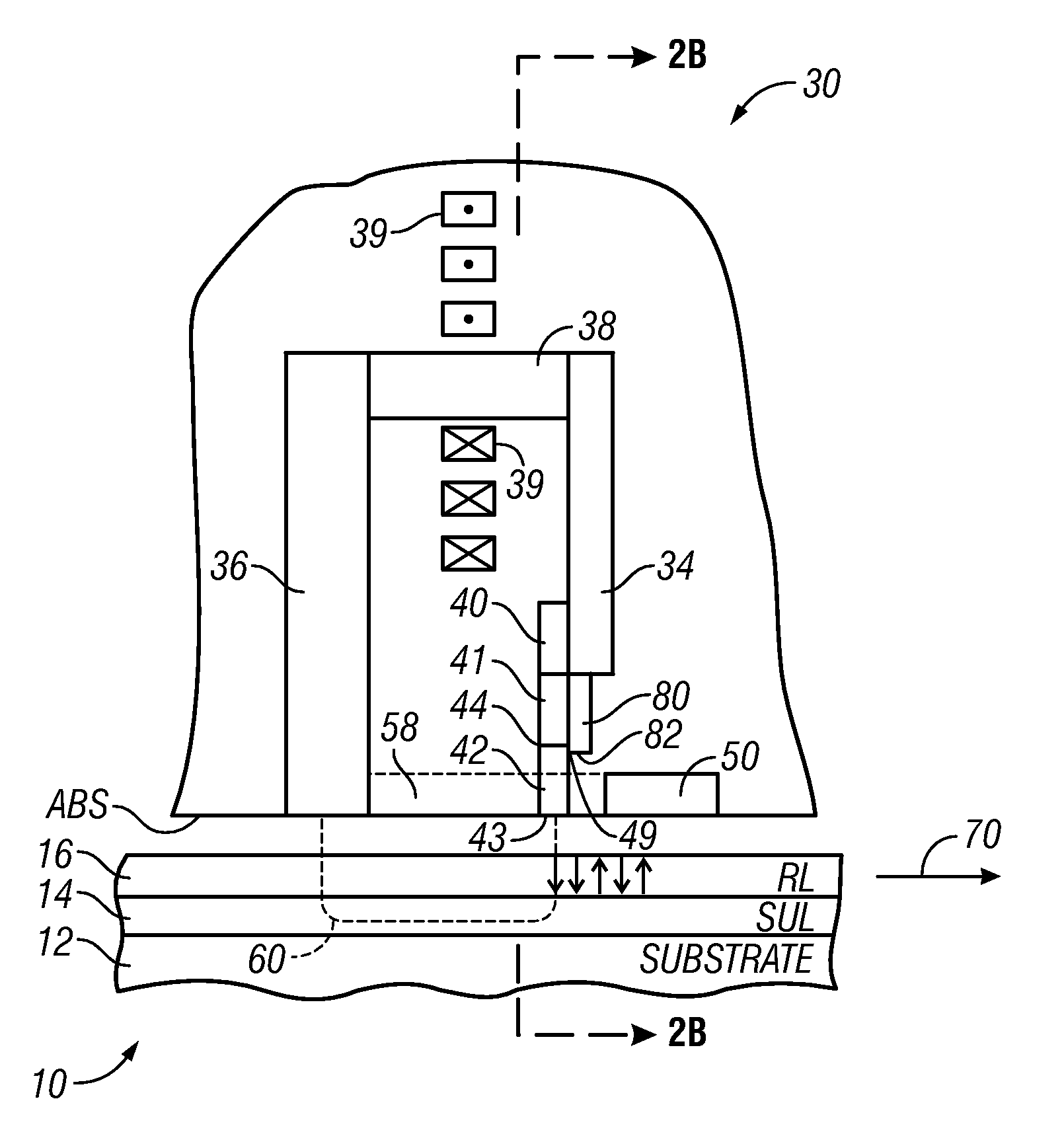
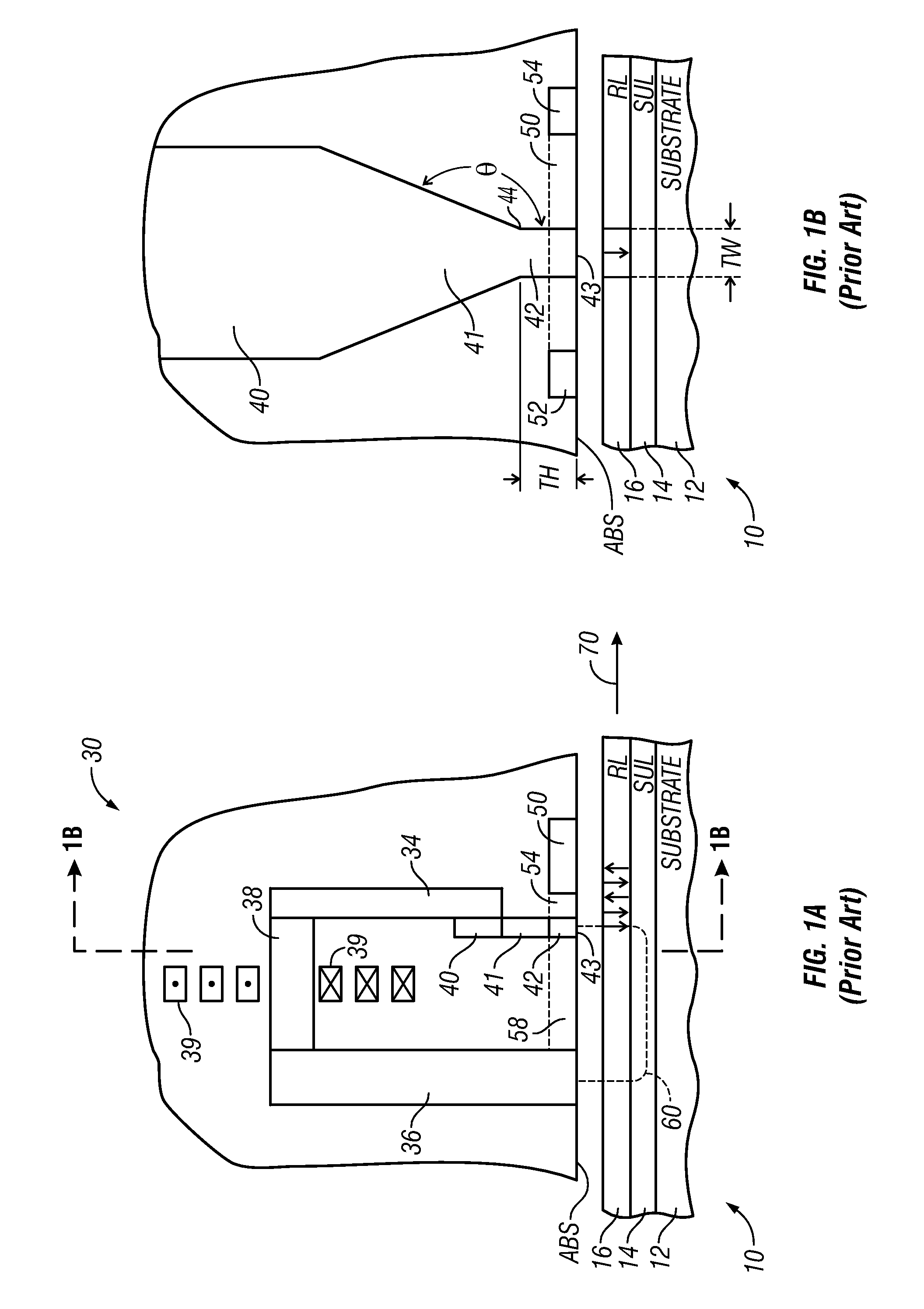
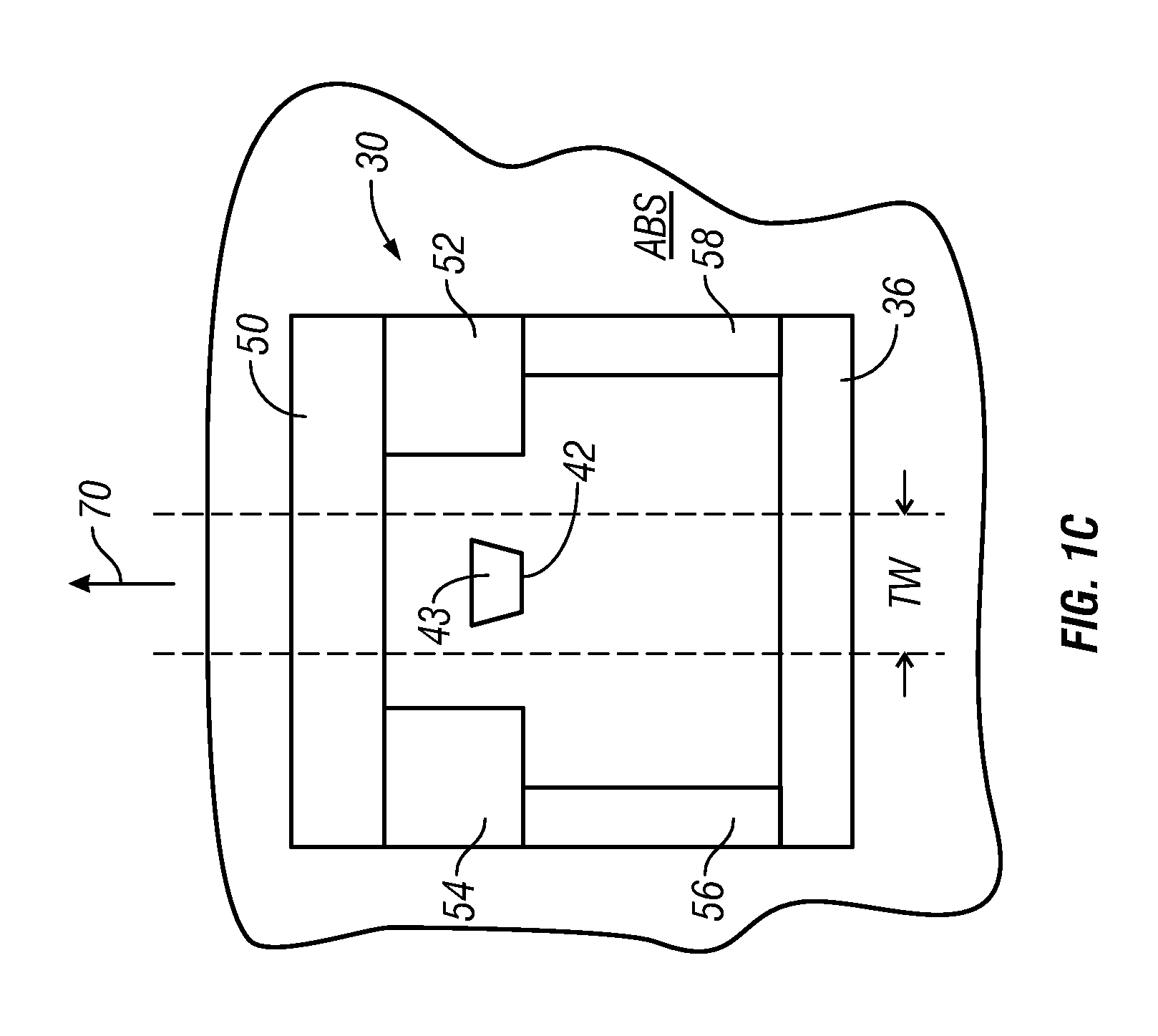
[0016]As shown in FIG. 1A, a “dual-layer” medium 10 includes a perpendicular magnetic data recording layer (RL) 16 on a “soft” or relatively low-coercivity magnetically permeable underlayer (SUL) 14 formed on the disk substrate 12. This type of medium is shown with a single write pole type of recording or write head 30. The recording head 30 includes a yoke made up of the main pole 34, flux return pole 36, and yoke stud 38 connecting the main pole and return pole 36; and a thin film coil 39 shown in section wrapped around yoke stud 38. A flared write pole (WP) 40 is part of the main pole 34 and has a flared portion 41 and a pole tip 42 with an end 43 that faces the outer surface of medium 10. Write current through coil 39 induces a magnetic field (shown by dashed line 60) from the WP 40 that passes through the RL 16 (to magnetize the region of the RL 16 beneath the WP 40), through the flux return path provided by the SUL 14, and back to the return pole 36. The recording head is typi...


PUM

PropertyMeasurementUnit
flare angleaaaaaaaaaa
angleaaaaaaaaaa
angleaaaaaaaaaa

Abstract

A perpendicular magnetic recording write head has a flux conductor in contact with the write pole. The flux conductor is substantially wider than the write pole tip in the cross-track direction and has a blunt end that is recessed from the pole tip end. The region of the flux conductor where its blunt end is in contact with the pole tip is the “choke” point for the write pole, i.e., the point where the flux density is highest. The flux conductor enables the write pole to be made with no flare, or with a flare angle and throat height with a much wider tolerance, which substantially simplifies the manufacturing process. The write head may have a trailing shield and side shields that substantially surround the write pole tip and remove stray fields that may be produced by the flux conductor, so that regions of the recording layer other than the track being written are not adversely affected.

Description

BACKGROUND OF THE INVENTION[0001]1. Field of the Invention[0002]This invention relates generally to perpendicular magnetic recording write heads, and more particularly to a write head with a write pole having improved flux conduction.[0003]2. Description of the Related Art[0004]Perpendicular magnetic recording, wherein the recorded bits are stored in a perpendicular or out-of-plane orientation in the recording layer, is a promising path toward ultra-high recording densities in magnetic recording hard disk drives. The recording head write pole must have a very narrow pole tip to achieve a narrow track width and thus high track density. However, the write pole must also be flared out into a larger flux-carrying body away from, but still relatively close to, the end of the write pole tip to achieve the required write field and write field gradient necessary for ultra-high density recording. The fabrication of the flared write pole, particularly the flare point location (which defines t...

Claims


Application Information

Patent Timeline
Patent Type & Authority Patents(United States)
IPC IPC(8): G11B5/10G11B5/127
CPCG11B5/11G11B5/1278G11B5/315G11B5/3146G11B5/3116
Inventor LE, QUANGNIX, JAMES L.ROBERTSON, NEIL LESLIESMITH, NEILVANDERHEIJDEN, PETRUS ANTONIUS
Owner WESTERN DIGITAL TECH INC
Why Eureka
Try Eureka