
Architecture for high speed class of service enabled linecard

a linecard and high-speed technology, applied in the field of linecards, can solve the problems of only limited success in providing the necessary increase in throughput speed, inability to quickly provide a range of services based on packet priority, and high packet latency, and achieve low latency, low cost and minimal packet delay.

Inactive Publication Date: 2009-07-07
CISCO TECH INC
View PDF11 Cites 38 Cited by
  • Summary
  • Abstract
  • Description
  • Claims
  • Application Information

AI Technical Summary

Benefits of technology

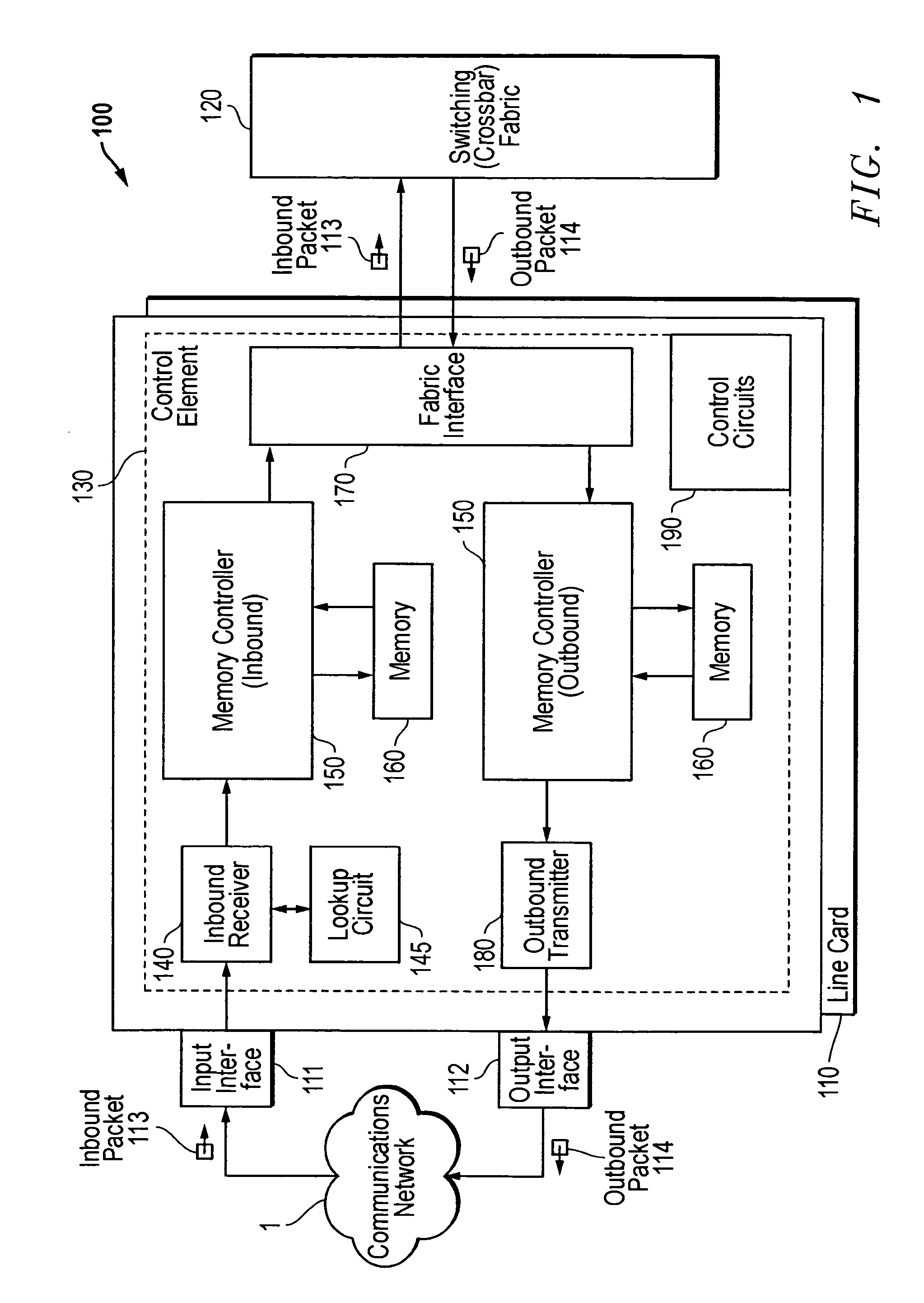
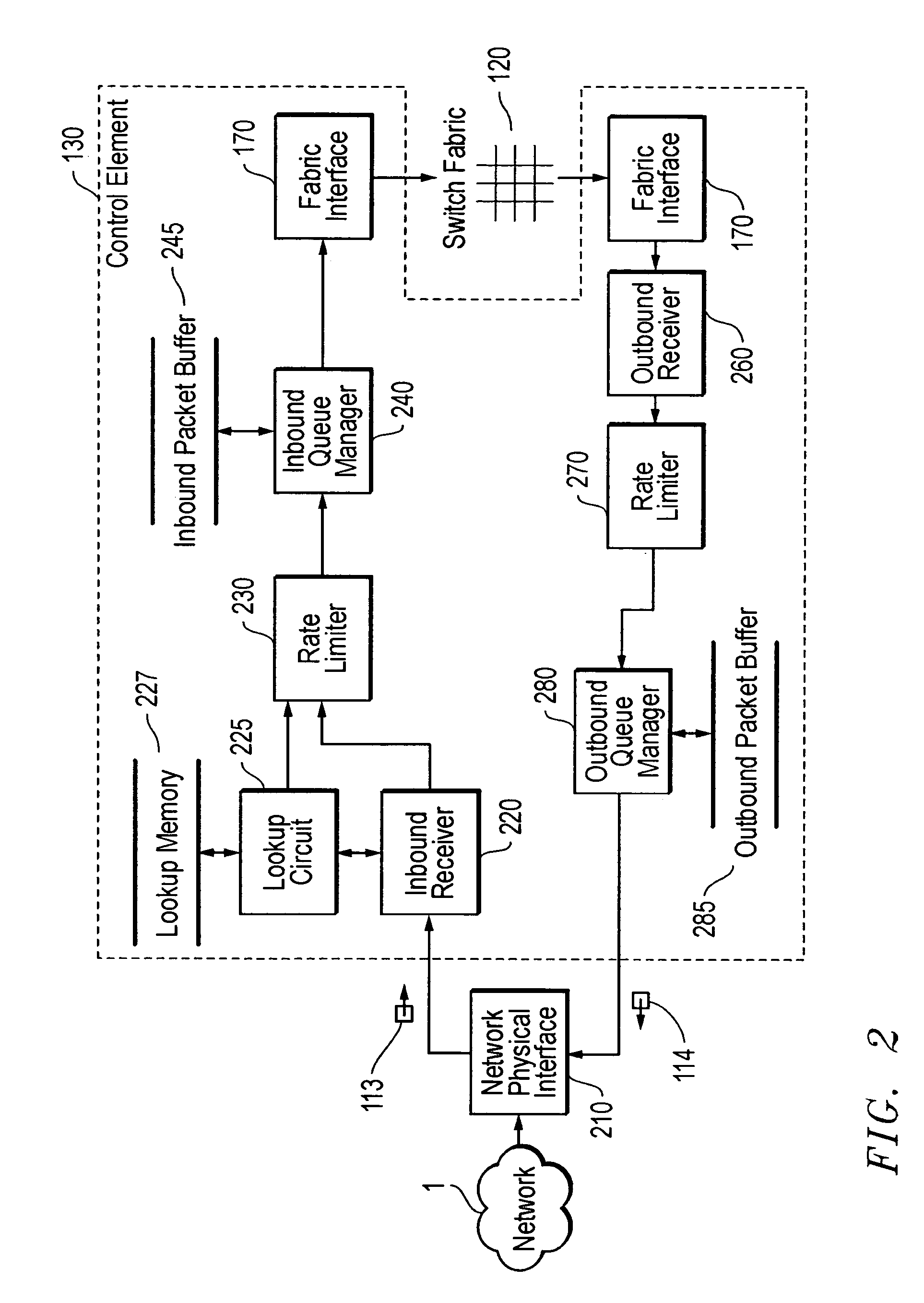
[0018]The present invention is a linecard architecture for high speed routing of data in a communications device. This architecture provides low latency routing based on packet priority because packet routing and processing occurs at line rate (i.e., at wire speed) for most operations. Comprised of an inbound receiver (including lookup and packet modification functions), queue manager, and outbound transmitter portions with associated network physical interfaces and a common device switching fabric, the architecture provides a distributed routing function with minimal packet delay.

Problems solved by technology

Attempts to scale prior art routers and switches to gigabit speed have shown that architectures that require a deep packet buffering prior to determining routing treatment suffer from high packet latency.
Distributed routing schemes, such as that described above wherein routing is performed immediately on packet receipt in each linecard, have had only limited success in providing the necessary increase in throughput speed.
A further drawback of prior art systems is their relative inability to rapidly provide a range of services based on packet priority, as represented by various fields in the packet header.

Method used


Image

  • Architecture for high speed class of service enabled linecard
  • Architecture for high speed class of service enabled linecard
  • Architecture for high speed class of service enabled linecard

Examples


embodiment

REPRESENTATIVE EMBODIMENT

[0114]In one embodiment of the present invention, shown in FIG. 7, the layer 3 (L3) switching function of control element 130 is distributed over three ASICs which perform the various functions described above, namely the RX, MCC, and TX ASICs.

[0115]The RX ASIC is used for four main functions: packet buffering control while the lookup is being performed (inbound receiver 220); IP routing lookups and IP checksum verification (lookup circuit 225); rate limiting, including CAR (rate limiter 230); and IP and tag level modifications.

[0116]The MCC ASIC function as the inbound queue manager 240 (also referred to as the “memory controller”). It is used to buffer packets waiting to go to the fabric.

[0117]The TX ASIC include outbound receiver 260, rate limiter 270, and outbound queue manager 280. The TX ASIC also adds the output encapsulation bytes and provides IP multicast features. The TX ASIC uses the queue management portion of the MCC ASIC to provide outbound que...


PUM


Abstract

A linecard architecture for high speed routing of data in a communications device. This architecture provides low latency routing based on packet priority: packet routing and processing occurs at line rate (wire speed) for most operations. A packet data stream is input to the inbound receiver, which uses a small packet FIFO to rapidly accumulate packet bytes. Once the header portion of the packet is received, the header alone is used to perform a high speed routing lookup and packet header modification. The queue manager then uses the class of service information in the packet header to enqueue the packet according to the required priority. Enqueued packets are buffered in a large memory space holding multiple packets prior to transmission across the device's switch fabric to the outbound linecard. On arrival at the outbound linecard, the packet is enqueued in the outbound transmitter portion of the linecard architecture. Another large, multi-packet memory structure, as employed in the inbound queue manager, provides buffering prior to transmission onto the network.

Description

CROSS-REFERENCE TO RELATED APPLICATIONS[0001]This application is a continuation of U.S. patent application Ser. No. 09 / 428,870, entitled “Architecture for High Speed Class of Service Enabled Line Card,” filed Oct. 27, 1999, now U.S. Pat. No. 6,687,247 and naming Bruce Wilford and Yie-Fong Dan as inventors, incorporated by reference herein in its entirety and for all purposes.BACKGROUND OF THE INVENTION[0002]1. Field of the Invention[0003]The present invention relates to communications devices, specifically linecards for interfacing communications devices to networks.[0004]2. Description of the Related Art[0005]In a communications network, routing devices receive messages at one of a set of input interfaces and forward them on to one of a set of output interfaces. Users typically require that such routing devices operate as quickly as possible in order to keep up with the high rate of incoming messages. In a packet routing network, wherein information is transmitted in discrete chunk...

Claims


Application Information

Patent Timeline
Patent Type & Authority Patents(United States)
IPC IPC(8): H04L12/28H04L12/18H04L12/56
CPCH04L12/5693H04L45/00H04L45/583H04L45/40H04L45/502H04L45/302H04L47/50
Inventor WILFORD, BRUCEDAN, YIE-FONG
Owner CISCO TECH INC
Learn More