Learning based logic diagnosis

a logic diagnosis and learning technology, applied in the field of identifying defects in semiconductor devices, can solve problems such as the inability to accurately detect and analyze faults, the failure of numerous devices to operate normally, and the difficulty of identifying and analyzing faults, etc., to achieve the effect of costly physical analysis

Inactive Publication Date: 2009-07-07
IBM CORP
View PDF32 Cites 7 Cited by
  • Summary
  • Abstract
  • Description
  • Claims
  • Application Information

AI Technical Summary

Problems solved by technology

Given the complexities involved in manufacturing a semiconductor device, it is not uncommon for a device to have numerous operational faults in the early production stages.
Identifying and analyzing these faults remains an important and costly challenge.
From the suspect set of nets, a costly physical analysis is then implemented to attempt to link the defect to a particular physical location and / or manufacturing step.
Unfortunately, the suspected set of nets often span across a large portion and various levels of the physical chip layout, thereby driving up the costs of the necessary physical analysis.

Method used


Image

  • Learning based logic diagnosis
  • Learning based logic diagnosis
  • Learning based logic diagnosis

Examples


Embodiment Construction

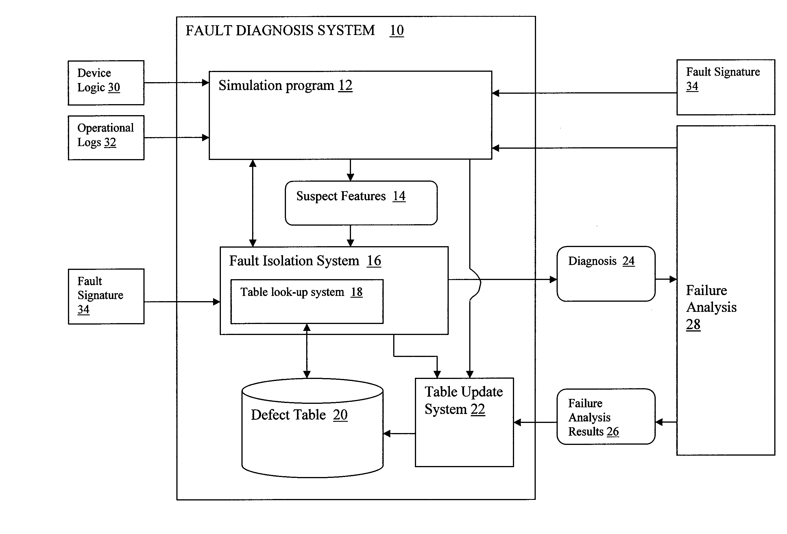
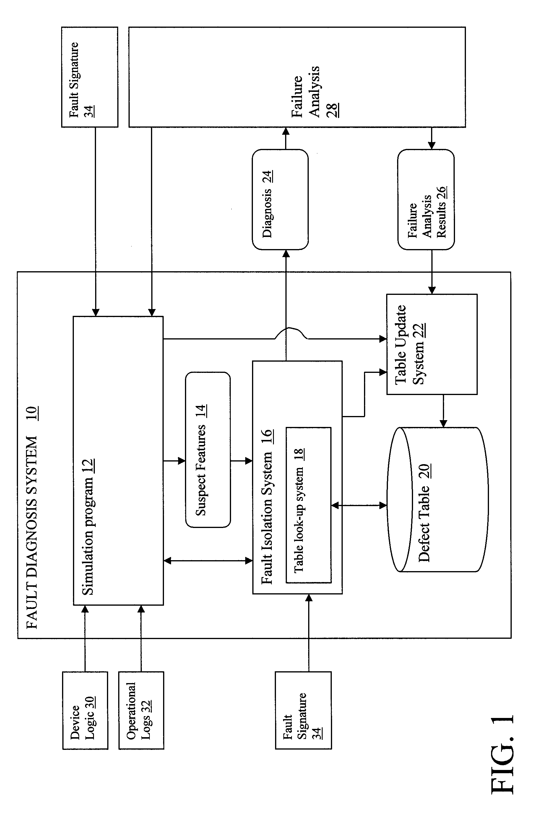
[0014]Referring now to the drawings, FIG. 1 depicts a fault diagnosis system 10 that facilitates the diagnosis of faults in an electronic device, such as an integrated circuit. Fault diagnosis system 10 utilizes an adaptive defect table 20, which includes a list of features that are associated with known failures, to facilitate the diagnosis process. The defect table 20 is utilized to help narrow down or identify one or more features that are likely to be causing a failure in a device currently being studied. For instance, defect table 20 may indicate that a particular net design is known to cause a short circuit. If the current device being analyzed includes the particular net and is exhibiting a failure that could be the result of a short circuit by that net, then the net design could be focused on as a highly likely cause of the failure.

[0015]As depicted, fault diagnosis system 10 comprises a simulation program 12 that generates a set of suspect features 14, which may cause a fai...


PUM


Abstract

A system and method for diagnosing a failure in an electronic device. A disclosed system comprises: a defect table that associates previously studied features with known failures; and a fault isolation system that compares an inputted set of suspected faulty device features with the previously studied features listed in the defect table in order to identify causes of the failure.

Description

BACKGROUND OF INVENTION[0001]1. Technical Field[0002]The present invention relates generally to identifying defects in a semiconductor device, and more specifically relates to a logic diagnosis system and method that utilizes a table of manufacturing characterization data to isolate and identify design features known to be error prone.[0003]2. Related Art[0004]Given the complexities involved in manufacturing a semiconductor device, it is not uncommon for a device to have numerous operational faults in the early production stages. Identifying and analyzing these faults remains an important and costly challenge.[0005]Traditional logic diagnosis relies on fault simulation software, which determines a set of logic nets (i.e., circuits) that are suspected to be at fault. Fault simulation software examines the logic of the faulty device, as well as logs of input and output values obtained from operating the actual device, and generates a list of suspect nets that might be causing the defe...

Claims


Application Information

Patent Timeline
Patent Type & Authority Patents(United States)
IPC IPC(8): G01R31/28G06F11/00G11C29/00
CPCG06F11/261G06F11/2252
Inventor ADKISSON, JAMES W.COHN, JOHN M.HUISMAN, LEENDERT M.KASSAB, MAROUNPFEIFER PASTEL, LEAH M.SWEENOR, DAVID E.
Owner IBM CORP
Why Eureka
Try Eureka