High-temperature pressure sensor and method of assembly

a high-temperature pressure sensor and high-temperature technology, applied in the field of sensors, can solve the problems of difficult proper use of electrical pressure probes such as piezoelectric sensors, limited piezoelectric pressure transducers, and inability to locate signal amplification electronics near the sensing element in these harsh environments

Active Publication Date: 2009-07-14
BAKER HUGHES INC
View PDF21 Cites 20 Cited by
  • Summary
  • Abstract
  • Description
  • Claims
  • Application Information

AI Technical Summary

Problems solved by technology

In internal combustion engines, engine knock and misfire are two undesirable phenomena directly related to pressure inside the cylinder of the engine where pressure measurements may be directly related to the overall engine performance.
Harsh environments characterize the operating conditions in these engines, among many other applications, where corrosive conditions, elevated temperatures, and electromagnetic interference, or EMI, make it difficult for the proper use of electrical pressure probes, such as piezoelectric sensors.
This is so because piezoelectric pressure transducers are limited due to signal variation caused by temperature and electromagnetic interference and dynamic response limitations caused by the need for the use of an intermediate interface between the environment and the sensing element.
Furthermore, signal amplification electronics cannot be located near the sensing element in these harsh environments.
However, one of the challenges of making a high-temperature optical dynamic pressure sensor is the development of an assembly, or packaging, that can survive elevated temperatures and minimally affect the sensor output.
However, the application of optical interferometers to high-temperature, harsh environments has been limited due to difficulties associated with packaging and reliability.
For example, due to variations in coefficient of thermal expansion of the different materials used, the stress state of optical cavities in conventional interferometers are significantly affected by temperature, causing unwanted changes in optical cavity dimensions and a high level of measurement uncertainty.
In addition, because of the difficulty in eliminating the relative motion of the fiber optic with respect to the optical cavity, additional undesired spectral signals are generated in the gaps between the fiber optic cable and the cavity, thus generating noise in the measured signal.
Furthermore, high temperature accelerates oxidation and corrosion of the packaging materials in the presence of contaminates from the environment and combustion by-products, such as sulfur, thus limiting the reliable functioning of the sensor, and diffusion of metals that lead to brittle intermetallic compounds and failure.

Method used


Image

  • High-temperature pressure sensor and method of assembly
  • High-temperature pressure sensor and method of assembly
  • High-temperature pressure sensor and method of assembly

Examples


example 1

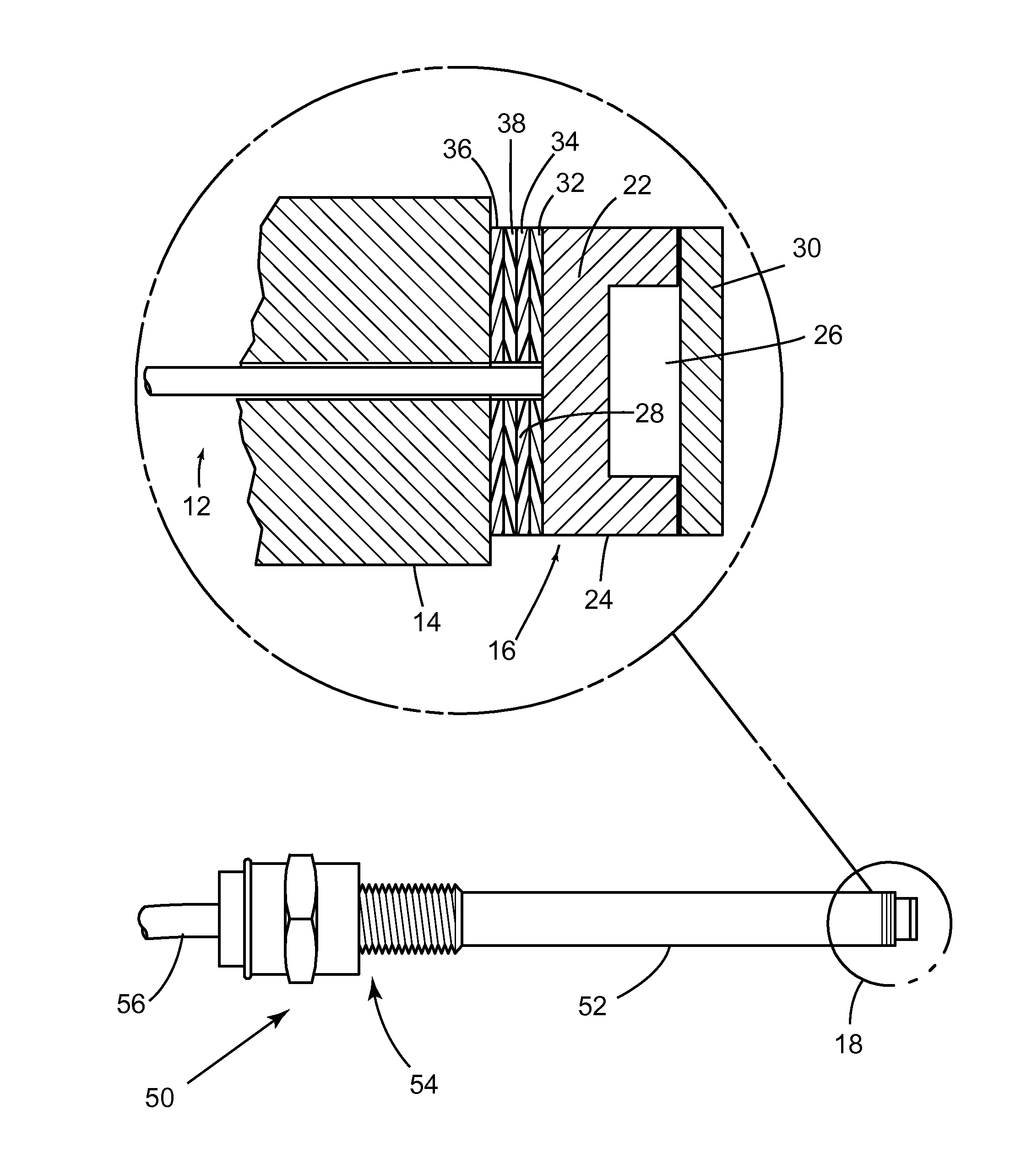
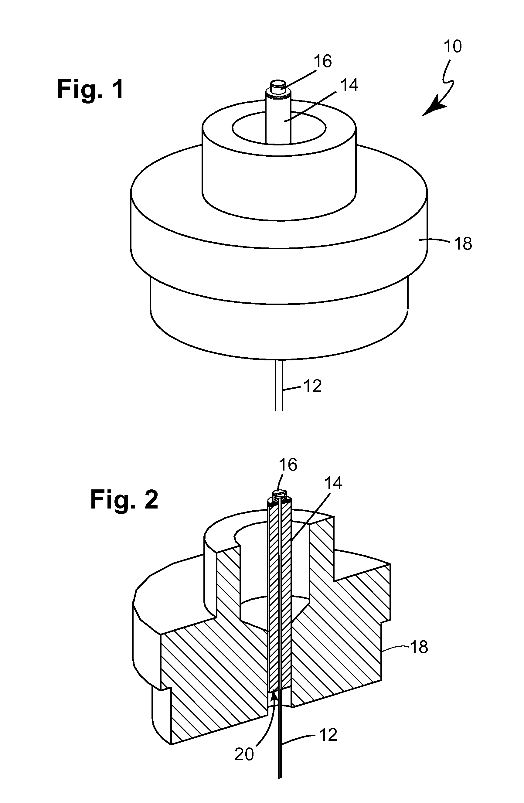
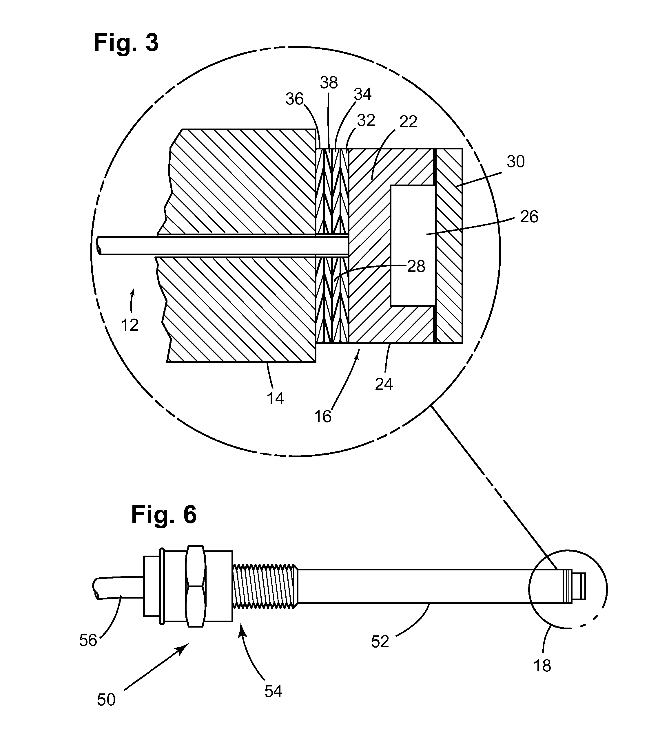
[0038]Based on the procedures summarized hereinabove in accordance to the disclosed invention, a pressure sensor as illustrated in FIGS. 1-5 was produced and tested. First, a Kovar ferrule subassembly was brazed to a stainless steel collar by first making one toroid out of a 15-mil Palcusil-10 wire with an inside diameter of about 0.043 in and subsequently sanding the entrance end of the ferrule and 10 mils from the end with a 400-grit paper to remove Ni / Au finish around the top of the countersink, thus preventing braze from wicking into the entrance hole. The ferrule was then placed into the drilled hole with the counter sink end leading into the collar and a braze ring was placed over the ferrule and pressed them into the gap between the strain relief and the collar hole, the resulting assembly being brazed at 860° C. for 5 minutes at temperature in a hydrogen atmosphere and leak tested.

[0039]In order to metallize the end of the ferrule proximal to the die, the brazed collar fixtu...

example 2

[0043]Based on the procedures summarized hereinabove in accordance to the disclosed invention, a pressure sensor as illustrated in FIGS. 7 was produced and tested. The steps of ferrule-to-collar braze, ferrule metallization, die-to-ferrule thermo-compression bonding, laser-welding assembly, and final assembly are similar to the ones disclosed with Example 1 and will not be repeated here.

[0044]In attaching the optical fiber cable, a glass bead was disposed on a metal-coated optical fiber a position about 3 in from the end thereof and the excess fiber was coiled up and placed onto a setter tile. The glass bead was molten by placing the setter tile into a furnace and heating the same in nitrogen atmosphere. The bead length in this particular example measured approximately 1.0 mm in length. A bath of ferric chloride solution was then prepared in a quantity proportional to 4 oz of ferric chloride to 16 oz of water and heated to 80° C. with constant stirring. Next, electroplating tape was...


PUM

PropertyMeasurementUnit
peak temperaturesaaaaaaaaaa
widthaaaaaaaaaa
heightaaaaaaaaaa

Abstract

A method for assembling a Fabry-Perot interferometer includes depositing a first metal layer on an end portion of a ferrule, depositing a second metal layer on a back portion of a die, placing the first metal layer and the second metal layer in contact with each other with respective first and second orifices aligned with respect to each other, and bonding the ferrule to the die by thermo compression. The resulting interferometer includes a glass die with a cavity, a silicon diaphragm disposed over the opening of the cavity and bonded to the glass die, a ferrule bonded to the glass die by thermo compression with the first and second orifices being aligned to each other, and an optical fiber inserted through the other end of the ferrule in direct contact to a back portion of the die and aligned with the first orifice.

Description

BACKGROUND OF THE INVENTION[0001]1. Field of the Invention[0002]The present invention relates in general to sensors and, more particularly, to a fiber-optic pressure sensor for use in hostile environments and methods of packaging the pressure sensor.[0003]2. Description of the Related Art[0004]In many engineering applications an accurate determination of both static and dynamic pressures is needed for optimized performance as well as the early detection of undesirable operating conditions. Consider, as an example, but not a limitation, the fact that in gas turbine and / or aircraft engines, overall efficiency is directly related to the maximum pressure in the cycle and compressor performance in such engines may be affected by sudden changes in pressure, particular during off-design performance. In internal combustion engines, engine knock and misfire are two undesirable phenomena directly related to pressure inside the cylinder of the engine where pressure measurements may be directly...

Claims


Application Information

Patent Timeline
Patent Type & Authority Patents(United States)
IPC IPC(8): G02B6/36G01B9/02
CPCB23K26/20G02B6/3624B23K2201/04Y10T156/10G02B6/3833B23K2201/36B23K26/21B23K2101/04B23K2101/36
Inventor KNOBLOCH, AARON JAYSHADDOCK, DAVID MULFORDESLER, DAVID RICHARDAIMI, MARCO FRANCESCOBYRD, DOUGLAS S.O'CONNOR, DAVID ROBERTKENNERLY, STACEY JOY
Owner BAKER HUGHES INC
Why Eureka
Try Eureka