Vehicle light control apparatus, system and method

a control apparatus and vehicle technology, applied in lighting and heating apparatus, lighting support devices, instruments, etc., can solve the problems of insufficient field of view of control apparatuses, inability to maintain a sufficient field of view, and inability to properly reduce headlight intensity, etc., to achieve the effect of reducing the intensity of illumination

Inactive Publication Date: 2009-07-14
DENSO CORP
View PDF10 Cites 9 Cited by
  • Summary
  • Abstract
  • Description
  • Claims
  • Application Information

AI Technical Summary

Benefits of technology

[0008]It is therefore an object of the present invention to provide a vehicle light control system and a vehicle light control apparatus, which maintain a desirable field of view at a subject vehicle even on a road having heavy traffic.
[0010]According to another aspect, in a vehicle light control method, a subject vehicle takes an image of other vehicles around the subject vehicle and receives identification signals unique to the other vehicles, respectively. The subject vehicle detects, in the other vehicles, another vehicle that has brightness exceeding a predetermined threshold in the image. The subject vehicle transmits a return signal identifying this vehicle. This vehicle reduces intensity of illumination of its headlight in response to the return signal transmitted from the subject vehicle.

Problems solved by technology

Therefore, if the driver of the oncoming vehicle is bad-mannered, the headlight intensity will not be properly reduced even if the driver is so prompted.
Thus, the driver may be dazzled by the light radiated from the headlights of the oncoming vehicle, and the field of view of the vehicle may consequently be obscured.
A subject vehicle will have many leading vehicles and oncoming vehicles on a road having heavy traffic, and the above vehicle light control apparatuses may not be able to maintain a sufficient field of view at the subject vehicle in such cases as exemplified below.
First, the vehicle light control apparatus disclosed in Document 1 indiscriminately transmits the control signal to the control apparatus of all vehicles concerned even when, for example, the quantity of light from only one of the plurality of vehicles is excessive.
It is not possible to request only the vehicle having the excessive quantity of light to reduce the intensity of light.
In this case, the problem of an insufficient field of view at the subject vehicle cannot be solved, unless an illumination adjusting process such as reducing light intensity is carried out at the other vehicle.
As thus described, either of the vehicle light control apparatus has not been able to sufficiently mitigate the problem of an insufficient field of view at a subject vehicle caused by an illumination adjustment failure such as an excessive quantity of light or a light distribution failure at another vehicle running near the same.

Method used


Image

  • Vehicle light control apparatus, system and method
  • Vehicle light control apparatus, system and method
  • Vehicle light control apparatus, system and method

Examples


Embodiment Construction

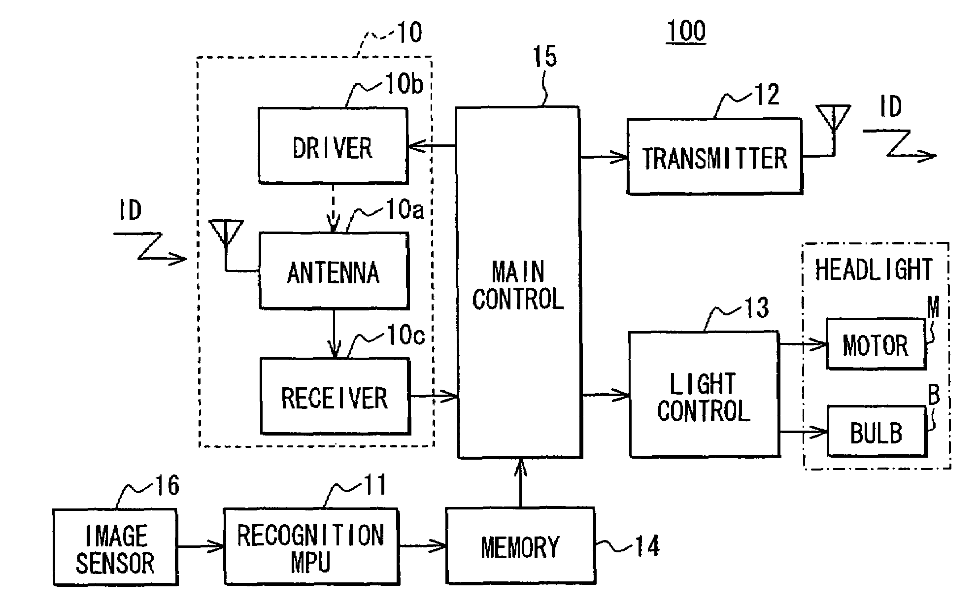
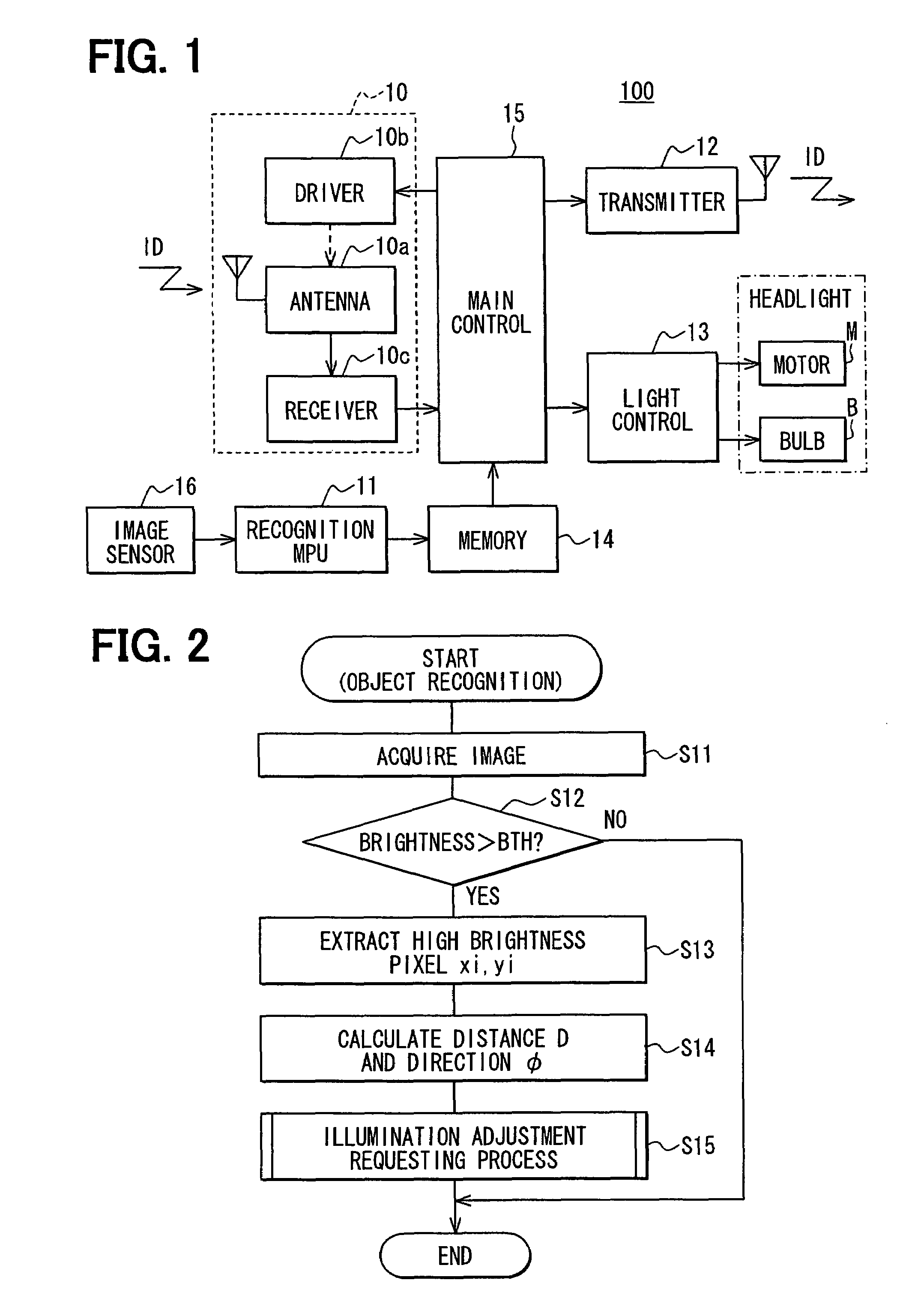
[0019]Referring first to FIG. 1, a vehicle light control apparatus in a subject vehicle 100 includes a signal receiver unit 10, an image recognition MPU (microprocessor unit) 11, a signal transmitter unit 12, a headlight control unit 13, and a memory 14 each of which is connected to a main control unit 15. In the present embodiment, a vehicle light control system is formed by a plurality of vehicles having such vehicle light control apparatuses, respectively.

[0020]The signal receiver unit 10 includes a directional antenna 10a, an antenna driver unit 10b including a pulse motor coupled with the directional antenna 10a, and a signal receiver circuit 10c electrically connected to the directional antenna 10a. The directional antenna 10a is disposed on a vehicle such that the direction pointed by the same can be varied with respect to the traveling direction of the vehicle. When a pulse signal is input from the main control unit 15, the pulse motor in the antenna driver unit 10b is drive...


PUM


Abstract

A vehicle light control apparatus includes an illumination control unit for executing illumination control on the mode of illumination of a subject vehicle based on signal transmission of a vehicle ID signal unique to the subject vehicle and signal reception of the vehicle ID signal unique to the subject vehicle. The control unit identifies a vehicle having brightness exceeding a predetermined threshold from an image of other vehicles acquired through an image recognition MPU as a vehicle having an illumination adjustment failure, and returns the same vehicle identification signal transmitted from the other vehicle thus identified to vehicles other than the subject vehicle.

Description

CROSS REFERENCE TO RELATED APPLICATION[0001]This application is based on and incorporates herein by reference Japanese Patent Application No. 2006-130809 filed on May 9, 2006.FIELD OF THE INVENTION[0002]The present invention relates to a vehicle light control apparatus for controlling a vehicle-mounted light such as a headlight and a tail light, a vehicle light control system using such a control apparatus, and a vehicle light control method among a plurality of vehicles.BACKGROUND OF THE INVENTION[0003]When a vehicle driver receives glaring light radiated from the headlights of an oncoming vehicle at night, it is a general practice to notify the driver of the oncoming vehicle of the fact by blinking the headlights to prompt him or her to reduce the intensity of the headlights through a change in the illumination mode, for example, from high beam to low beam. However, it depends on the mind of the driver of the oncoming vehicle whether the intensity of the headlights is reduced or n...

Claims


Application Information

Patent Timeline
Patent Type & Authority Patents(United States)
IPC IPC(8): B60Q1/00B60Q1/26G01B5/00G05D1/00G06F7/00G08B1/08G08G1/00G08G1/01G08G1/04
CPCB60Q1/1423G08G1/162B60Q2300/42B60Q1/547
Inventor YAMAMOTO, ATSUSHI
Owner DENSO CORP
Why Eureka
Try Eureka