

Light source unit, method of manufacturing light source unit, and projector
a technology of light source unit and manufacturing method, which is applied in the field of light source unit, can solve the problems of low reflectivity efficiency of the reflecting film, low luminous efficiency of the light emitted from the light emitting section, and lowering the illumination intensity of the light source unit, and achieves the effect of significantly enhancing the luminous efficiency of the light sour
- Summary
- Abstract
- Description
- Claims
- Application Information
AI Technical Summary
Benefits of technology
Problems solved by technology
Method used
Image

Examples
first exemplary embodiment
1 First Exemplary Embodiment
Structure of Projector
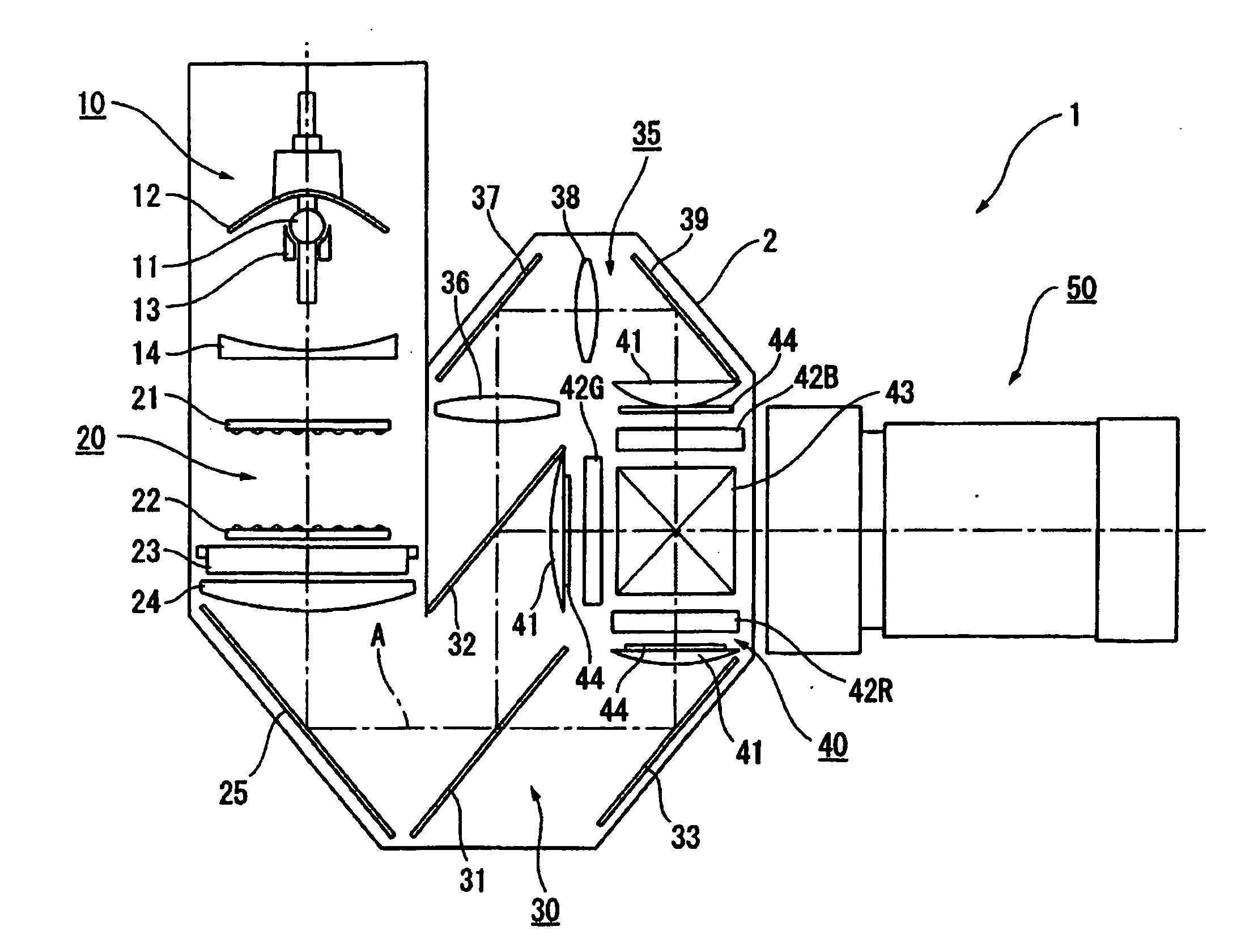
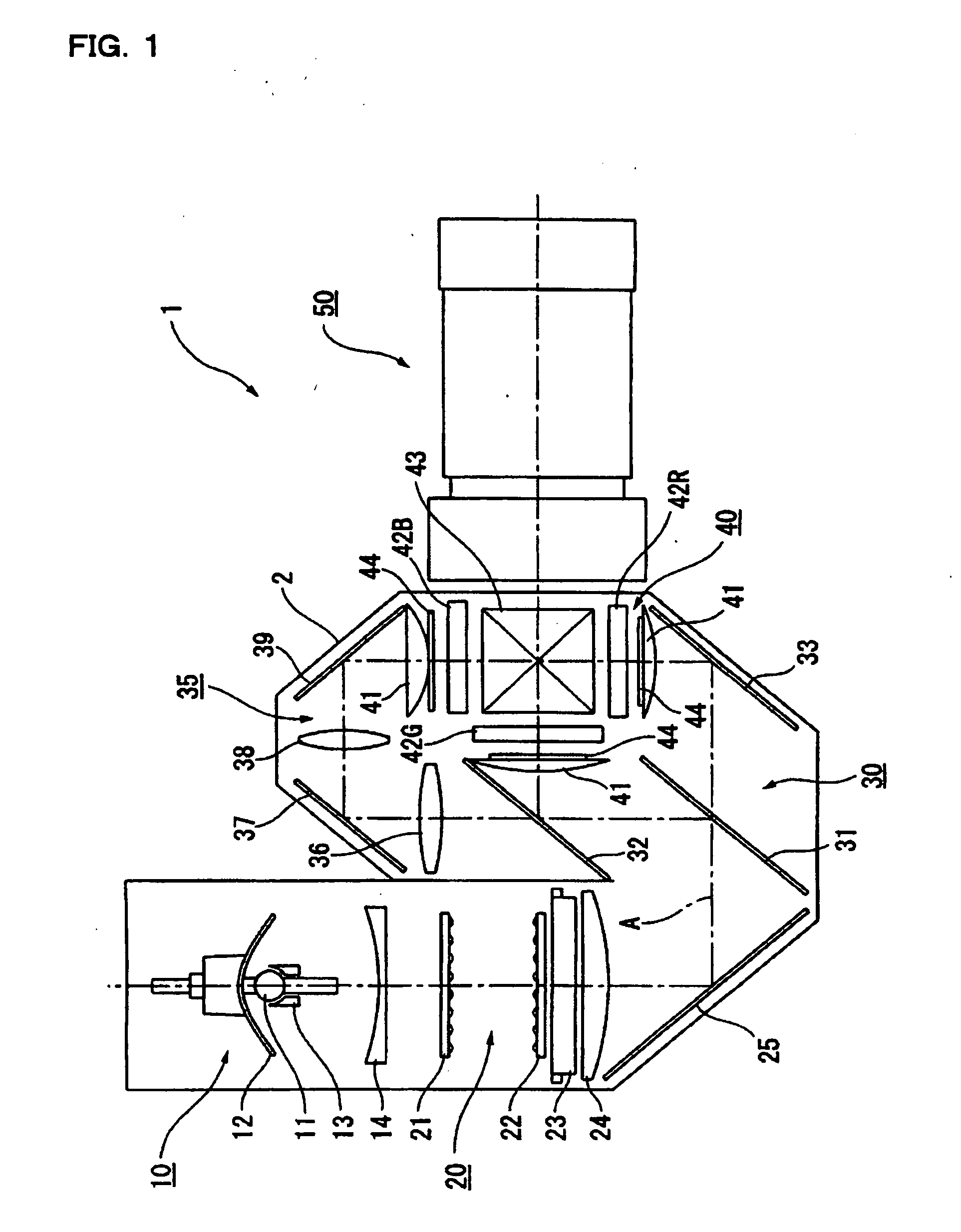
[0107]FIG. 1 is a schematic showing an optical system of a projector 1 according to a first exemplary embodiment of the present invention. The projector 1 is an optical instrument to form an optical image by modulating a luminous flux emitted from a light source according to image information and projecting an enlarged image on a screen, and includes a light source unit 10, an uniformly illuminating optical system 20, a color separating optical system 30, a relay optical system 35, an optical device 40, and a projecting optical system 50. Optical elements constituting the optical systems 20-35 are positionally adjusted and stored in an optical component enclosure 2 having a preset illumination axis A.
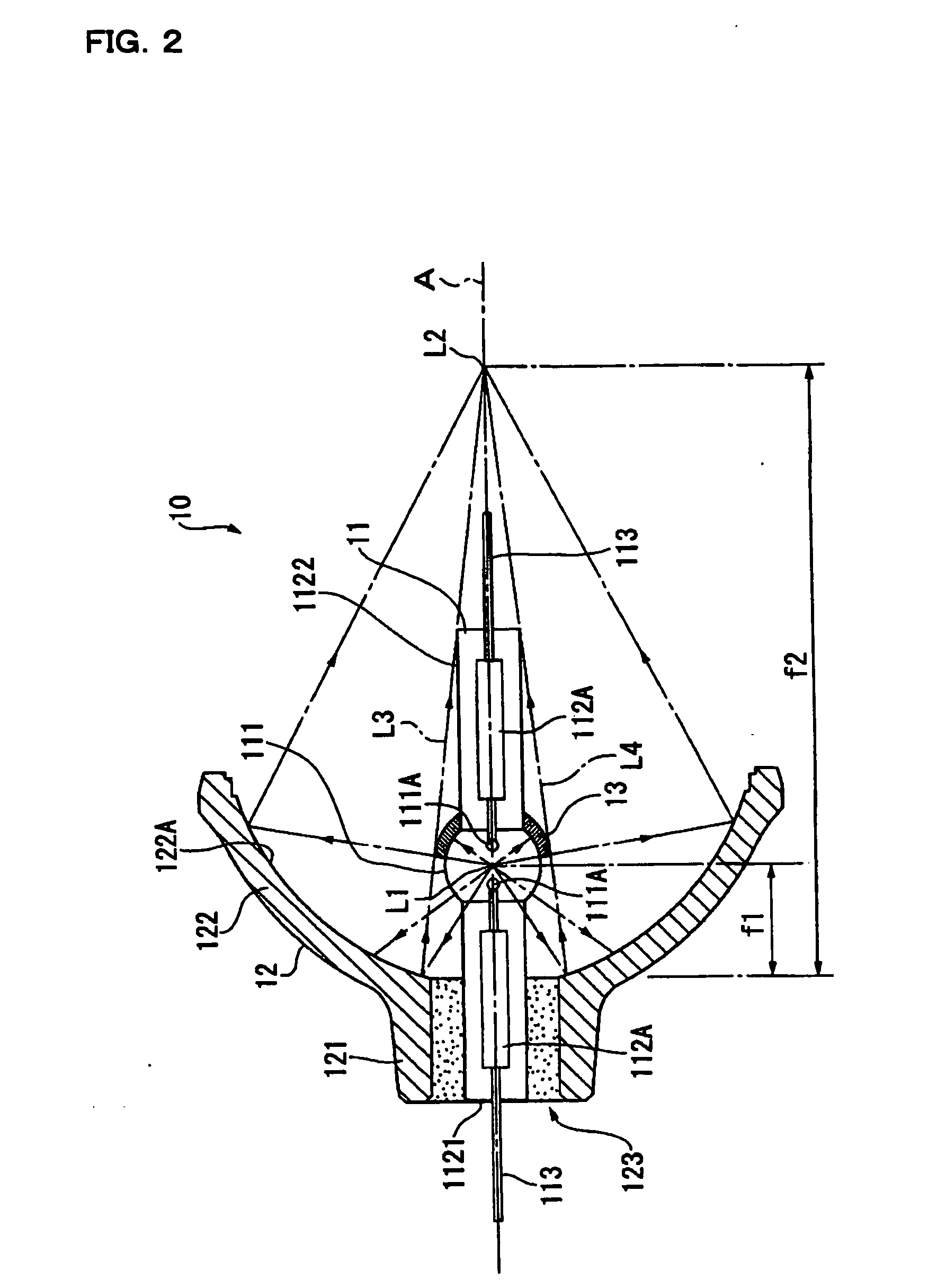
[0108] The light source unit 10 emits a luminous flux radiated from a light source lamp 11 in a certain uniform direction to illuminate the optical device 40 and, though details are described later, includes the light source lamp 11, ...
second exemplary embodiment
2 Second Exemplary Embodiment
[0195] Subsequently, a second exemplary embodiment of the present invention will be described. In the description below, parts and members which have already been described are represented by the identical numerals and the description will be omitted or simplified.
[0196] In the first exemplary embodiment described above, the outer peripheral surface 132 of the secondary reflecting mirror 13 is a curved surface so as to follow the curvature of the reflecting surface 131, and the secondary reflecting mirror 13 is formed with the reflecting surface 131 and the outer peripheral surface 132 by polishing the cylindrical member 136.
[0197] In contrast, secondary reflecting mirrors 71-74 according to the second exemplary embodiment are, as shown in FIG. 14 and FIG. 15, different in that outer peripheral surfaces 712, 722, 732, 742 are of a substantially cylindrical shape or of a substantially truncated conical shape. The reflecting surface 131 of each of the se...
third exemplary embodiment
3 Third Exemplary Embodiment
[0211] Subsequently, a third exemplary embodiment of the present invention will be described. In the description below, parts and members which have already been described are represented by the identical numerals and the description will be omitted or simplified.
[0212] In the case of the secondary reflecting mirror 13 according to the first exemplary embodiment and the secondary reflecting mirrors 71, 73, 74 according to the second exemplary embodiment, the meeting points between the outer peripheral surfaces 132, 712, 732, 742 and the adhering surface 134 are not machined at all, as shown in FIG. 4, FIG. 14, and FIG. 15.
[0213] In contrast, as shown in FIG. 16(A), the secondary reflecting mirror 76 according to the third exemplary embodiment is different in that a plurality of notched grooves 761 are formed along the ridged line at the meeting point between the outer peripheral surface 132 and the adhering surface 134.
[0214] The notched grooves 761 ar...
PUM
| Property | Measurement | Unit |
|---|---|---|
| angle | aaaaa | aaaaa |
| angle | aaaaa | aaaaa |
| angle | aaaaa | aaaaa |
Abstract
Description
Claims
Application Information