
Distortion compensation amplifying apparatus and base station

a technology of distortion compensation and amplifier, which is applied in the direction of amplifier modifications, multiplex communication, and amplifier details to reduce non-linear distortion, can solve the problems of reducing the signal power range, difficulty in finely storing the distortion compensation coefficient according to input level, and affecting the accuracy of the output. , to achieve the effect of reducing the memory capacity of the storing unit, reducing the loss of distortion characteristics, and high accuracy

Inactive Publication Date: 2009-07-14
FUJITSU LTD
View PDF41 Cites 13 Cited by
  • Summary
  • Abstract
  • Description
  • Claims
  • Application Information

AI Technical Summary

Benefits of technology

[0023]The present invention has been developed with a view to eliminating these problems, and it is therefore an object of the invention to provide, in a code division multiplex access network, a distortion compensation amplifying apparatus and a base station, capable of carrying out the distortion compensation on an amplifier with high accuracy through quick response even if inputted signal power varies rapidly.
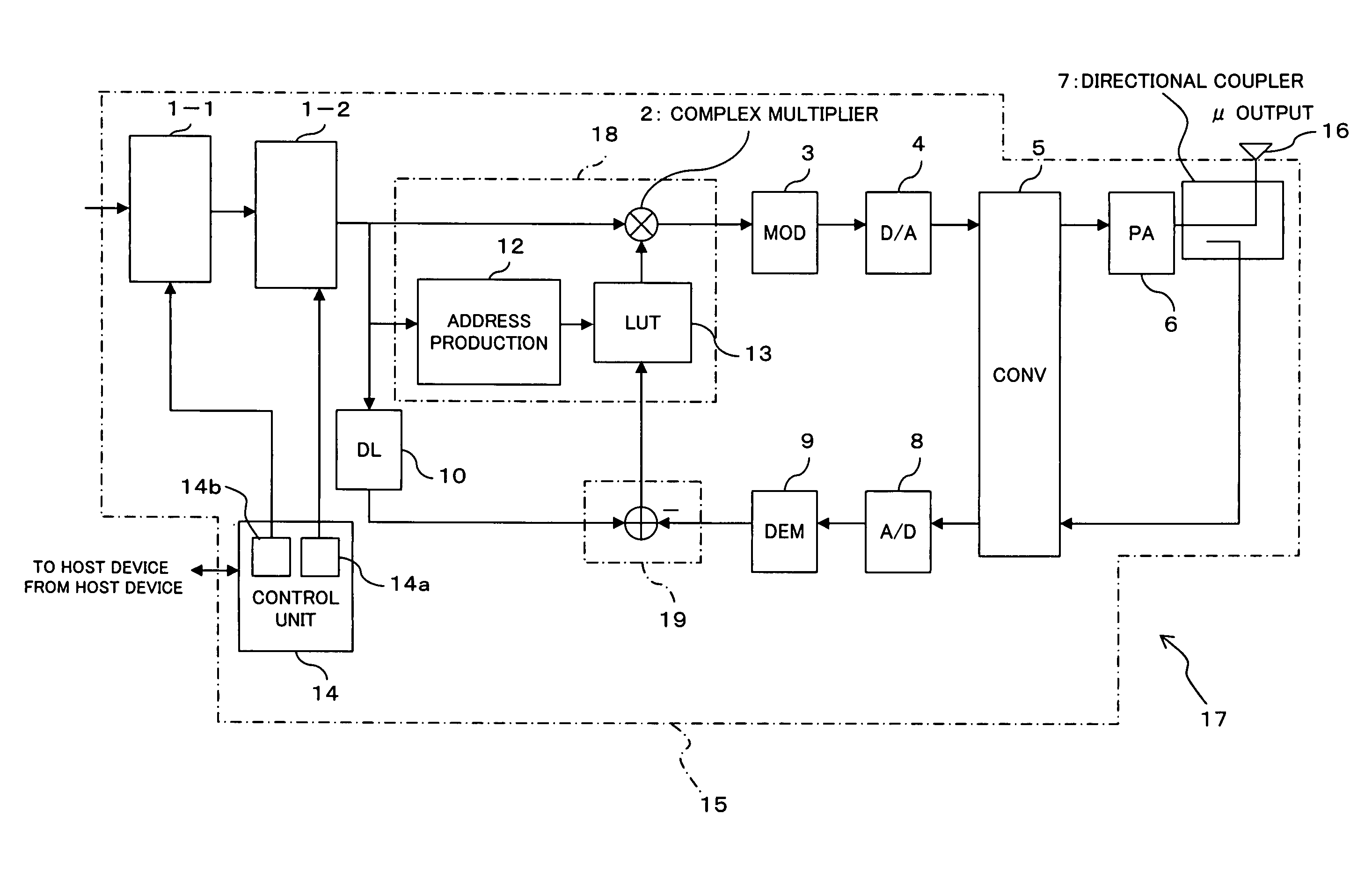
[0046]Thus, according to the present invention, since the renewal of the distortion compensation coefficient can be complemented in the renewing unit on the basis of a result of amplification in the amplifier with respect to a signal undergoing the code division multiplex processing in the pseudo-signal multiplexing unit, even if the signal power increases relatively fast and a signal with power out of rating is inputted to the amplifier, since the distortion compensation coefficient can be stored through the renewal processing in the renewing unit, a quick response becomes feasible to achieve the distortion compensation with high accuracy.
[0047]In addition, since a pseudo signal can properly be code-division-multiplexed during an operation of the apparatus owing to the employment of the control unit, with respect to off-rating regions, the renewing unit can update a region exposed to temperature variation or the like at the location and, hence, as the specification of the apparatus at the shipment from a factory, there is no need to store distortion compensation coefficients in an particularly high output region, which can minimize the memory capacity of the storing unit which is for storing the distortion compensation coefficients.
[0048]Still additionally, it is possible to narrow the signal power range in which the distortion compensation coefficients are to be stored as rating, which enables shortening a training time taken for setting storage values in the storing unit which stores distortion compensation coefficients before shipment of the apparatus.

Problems solved by technology

HEI 9-69733, the distortion compensation is made through the control for reducing the difference between a transmitted signal and a feedback signal to the utmost, and with respect to the distortion compensation coefficient needed for the distortion compensation, the initial value is stored through the training according to a pattern (rating) determined in a factory under limited time, which makes it difficult to finely store the distortion compensation coefficient according to the input level.
Accordingly, for example, as indicated by a time point A in FIG. 10, in a case in which a signal remote temporarily from the rating during the operation and insufficient (high) in training is suddenly inputted to the power amplifier, difficulty is encountered in outputting an appropriate distortion compensation coefficient immediately and, because of the renewal of the table based on the distortion, it takes time until the distortion compensation coefficient reaches the convergence, so the degradation of the distortion characteristic occurs in the meantime.
In addition, taking into consideration the influence of a variation of the distortion characteristic stemming from aged deterioration of the power amplifier and temperature variation, although, when the call quantity is large at all times, the error quantity becomes small because a table has been produced to store distortion compensation coefficients in high-output conditions, in the normal actual operation in which the frequency of occurrence of a high output is relatively low, the error of the distortion compensation coefficient stored in the table become relatively large.
On the other hand, although it can be considered that tables are finely produced according to the magnitude (small, intermediate, large) of signal level at the training to shorten the table convergence, the test time in the factory becomes longer, which leads to an increase in cost.
HEI 9-102759, since a training signal can be transmitted only during the transmission downtime, for a communication network such as the code division multiplex access in which there is basically no need for the transmission downtime and the communications are made in a state where difficulty is encountered in securing such a time period, if the transmission power increases rapidly, difficulty is experienced in quickly achieving the table convergence, which makes it difficult to maintain the communication quality.

Method used


Image

  • Distortion compensation amplifying apparatus and base station
  • Distortion compensation amplifying apparatus and base station
  • Distortion compensation amplifying apparatus and base station

Examples


first embodiment

[A] Description of First Embodiment

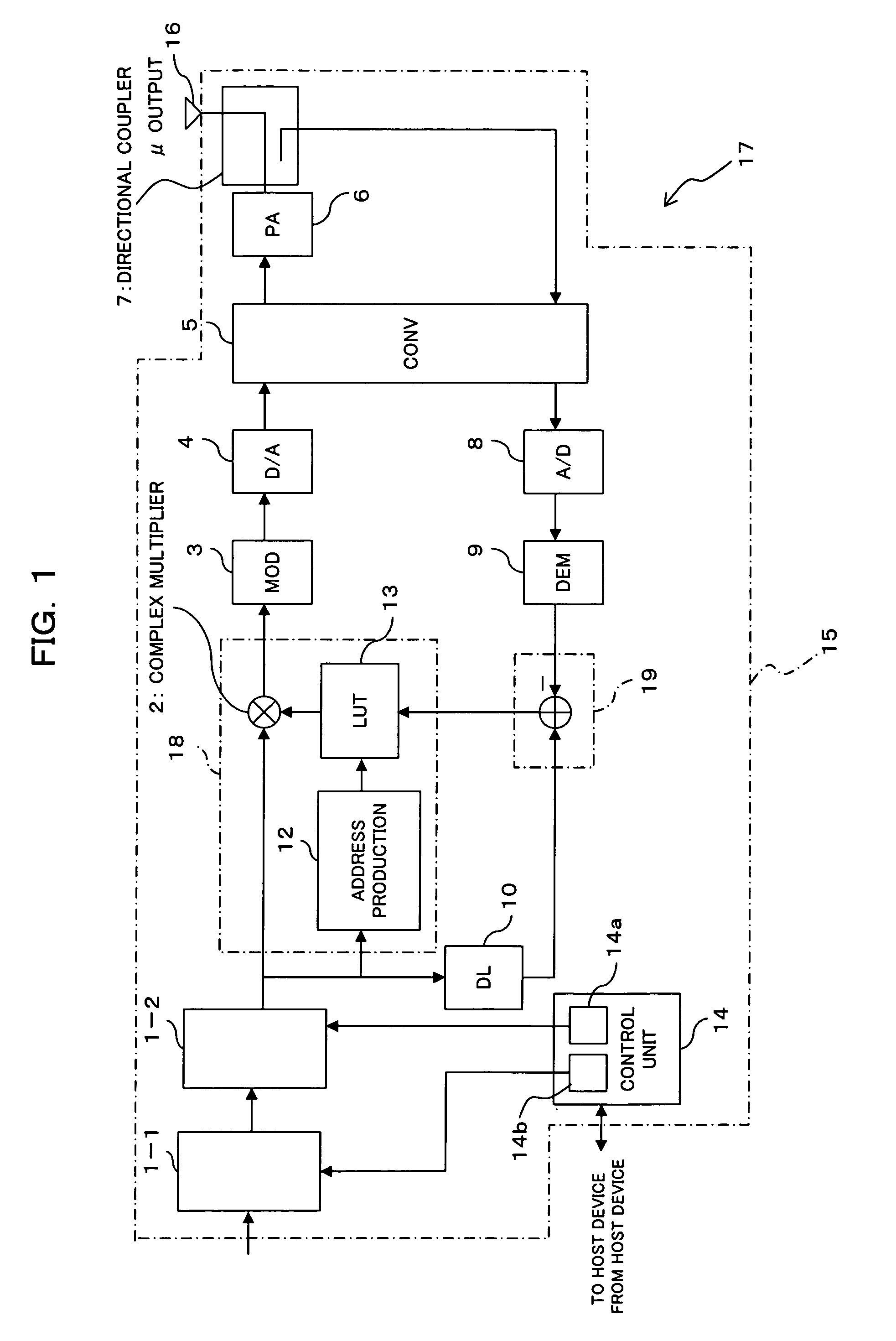
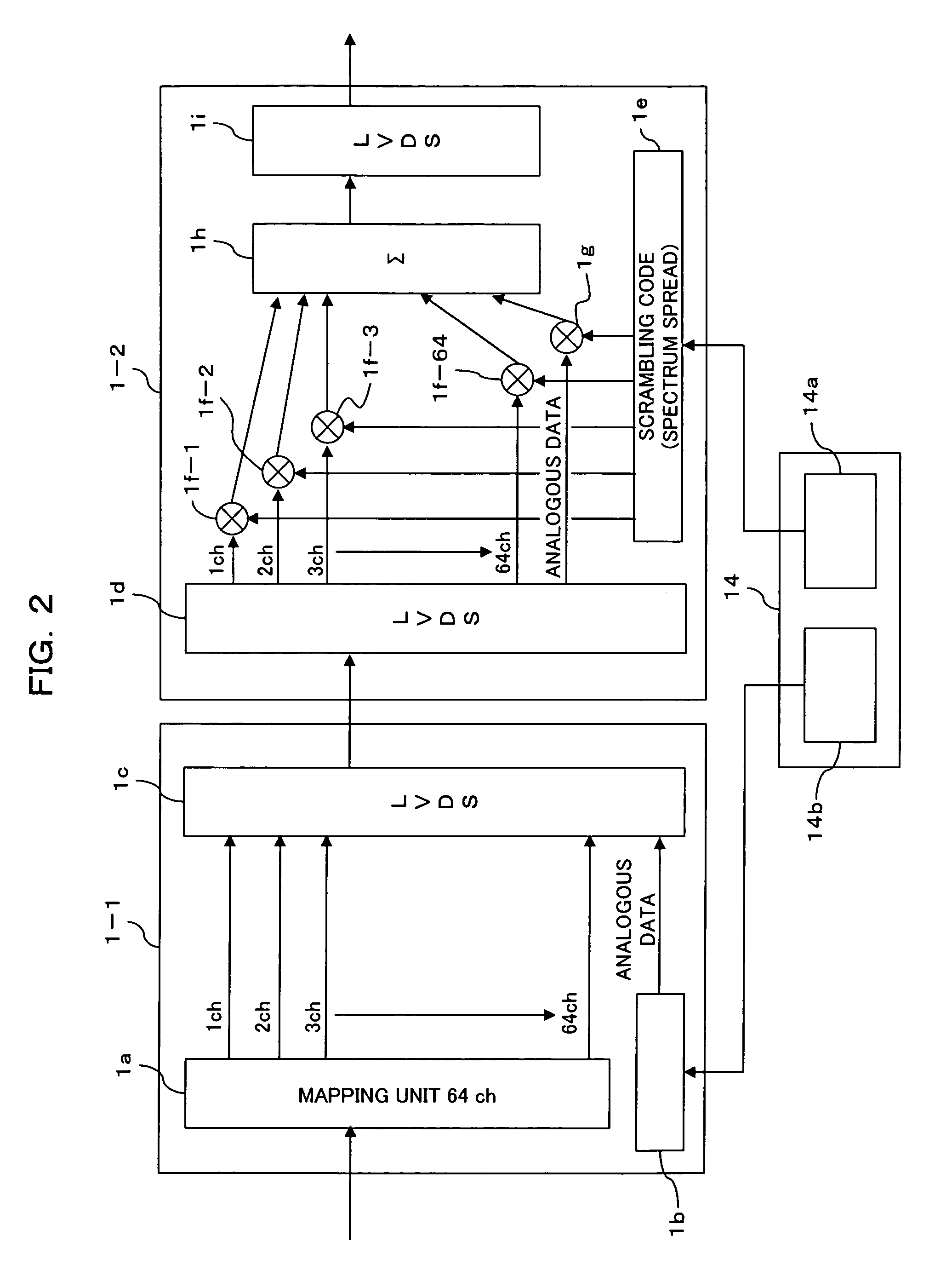
[0060]FIG. 1 is a block diagram showing a transmitting apparatus including a distortion compensation amplifying apparatus according to a first embodiment of the present invention. In FIG. 1, the distortion compensation amplifying apparatus 15 of the transmitting apparatus is for amplifying a code-division-multiplexed signal while carrying out the distortion compensation, with the signal amplified in the distortion compensation amplifying apparatus 15 being radio-transmitted through an antenna 16.

[0061]That is, the distortion compensation amplifier 15 and the antenna 16 constitutes the transmitting apparatus. This transmitting apparatus can be constructed as a transmitting unit of a base station 17 in a mobile communication network employing a CDMA communication system, and a spectrum-spread signal is transmitted to terminals existing in a covering area of this base station 17 in a state amplified by a power amplifier having a distortion compensatio...

second embodiment

[B] Description of Second Embodiment

[0118]FIG. 5 is a block diagram showing a distortion compensation amplifying apparatus according to a second embodiment of the present invention. This distortion compensation amplifying apparatus 25 shown in FIG. 5 is also designed to perform the amplification while carrying out the distortion compensation with respect to a signal code-division-multiplexed. This distortion compensation amplifying apparatus 25 and an antenna 16 constitute a transmitting apparatus, and a transmitting unit 21 as this transmitting apparatus and a receiving unit 22 organize a base station 27 in a radio network.

[0119]As compared with the first embodiment described above, as different points, the transmitting unit employing the distortion compensation amplifying apparatus according to the second embodiment is made to transmit a signal code-division-multiplexed using multi-carrier (in this case, four carriers Cr1 to Cr4) for example, shown in FIG. 7 and the control unit 1...


PUM


Abstract

In a network employing code division multiplex access, a distortion compensation amplifying apparatus is provided which is capable of making quick response to carry out the distortion compensation with high accuracy even if the signal power to be inputted thereto varies rapidly. In this distortion compensation amplifying apparatus, the renewal of a distortion compensation coefficient in a renewing unit is complemented on the basis of a result of amplification in an amplifier with respect to a signal code-division-multiplexed in a pseudo-signal multiplexing unit.

Description

BACKGROUND OF THE INVENTION[0001]1) Field of the Invention[0002]The present invention relates to a transmitting apparatus on a communication network, preferably, to a transmitting apparatus on a radio communication network, and more particularly to a distortion compensation amplifying apparatus suitable for use in a transmitting unit constituting a base station, and it relates to a base station suitable for use in a radio network.[0003]2) Description of the Related Art[0004]FIG. 9 is a block diagram showing a transmitting apparatus in a base station which employs CDMA communications including a conventional digital pre-distortion compensation amplifying apparatus (digital pre-distortion AMP). In FIG. 9, a digital pre-distortion compensating amplifier 115 is connected to an antenna 116 to serve as a transmitting apparatus 117 to carry out radio transmissions of signals through the antenna 116.[0005]This distortion compensation amplifier 115, shown in FIG. 9, is for use in a transmitt...

Claims


Application Information

Patent Timeline
Patent Type & Authority Patents(United States)
IPC IPC(8): H04B1/04H03F1/32H04B1/707H03F3/24H04J13/00H04L27/26H04L27/36
CPCH03F1/3247H03F1/3294H04L27/368H03F2201/3233H04B1/707H03F2201/3206
Inventor WATABE, MASAYUKIFUNYU, YASUHITOABE, HIROAKIKAWANO, HISATO
Owner FUJITSU LTD
Learn More