Self-illuminated sighting device

a self-illuminating, sighting device technology, applied in the direction of sighting devices, weapons, weapon components, etc., can solve the problems of short fiber optic segments with limited light gathering ability, sight points that may not have enough brightness to satisfy some users, and less than adequate illumination of sight points

Active Publication Date: 2009-07-21
GOOD SPORTSMAN MARKETING LLC
View PDF26 Cites 78 Cited by
  • Summary
  • Abstract
  • Description
  • Claims
  • Application Information

AI Technical Summary

Problems solved by technology

However, the short segments of fiber optic have a limited light gathering ability.
Under very low lighting conditions, such as at late dusk or early dawn, the sight point may not have sufficient brightness to satisfy some users.
However, installation of the individual components, such as the artificial light source and light gathering fiber optic, into the cavity of a gun sight or the like is time consuming and error prone since it is difficult to determine through the opaque sight blade whether the components are axially aligned, resulting in less than adequate illumination of the sight point.

Method used


Image

  • Self-illuminated sighting device
  • Self-illuminated sighting device
  • Self-illuminated sighting device

Examples


Embodiment Construction

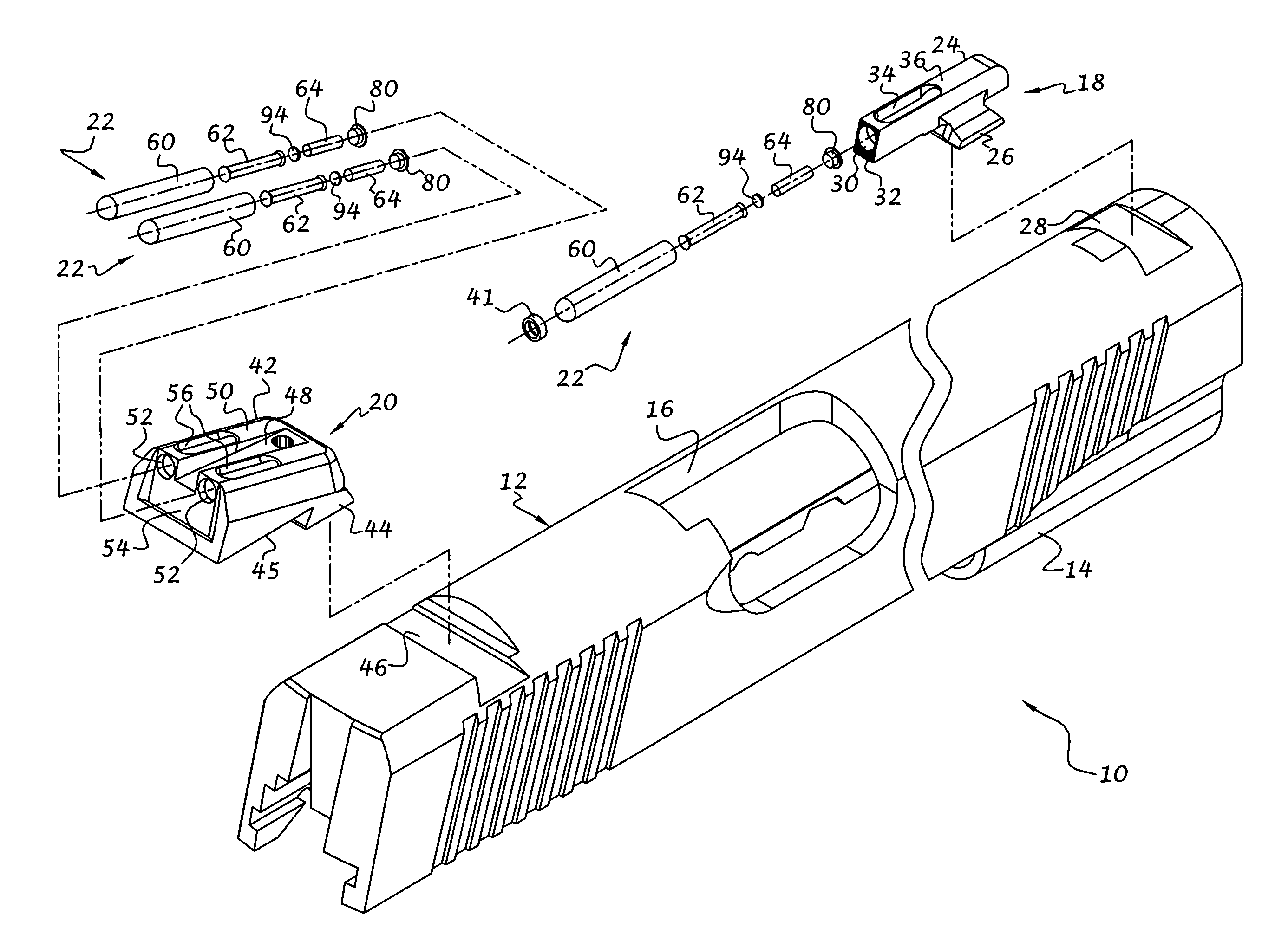
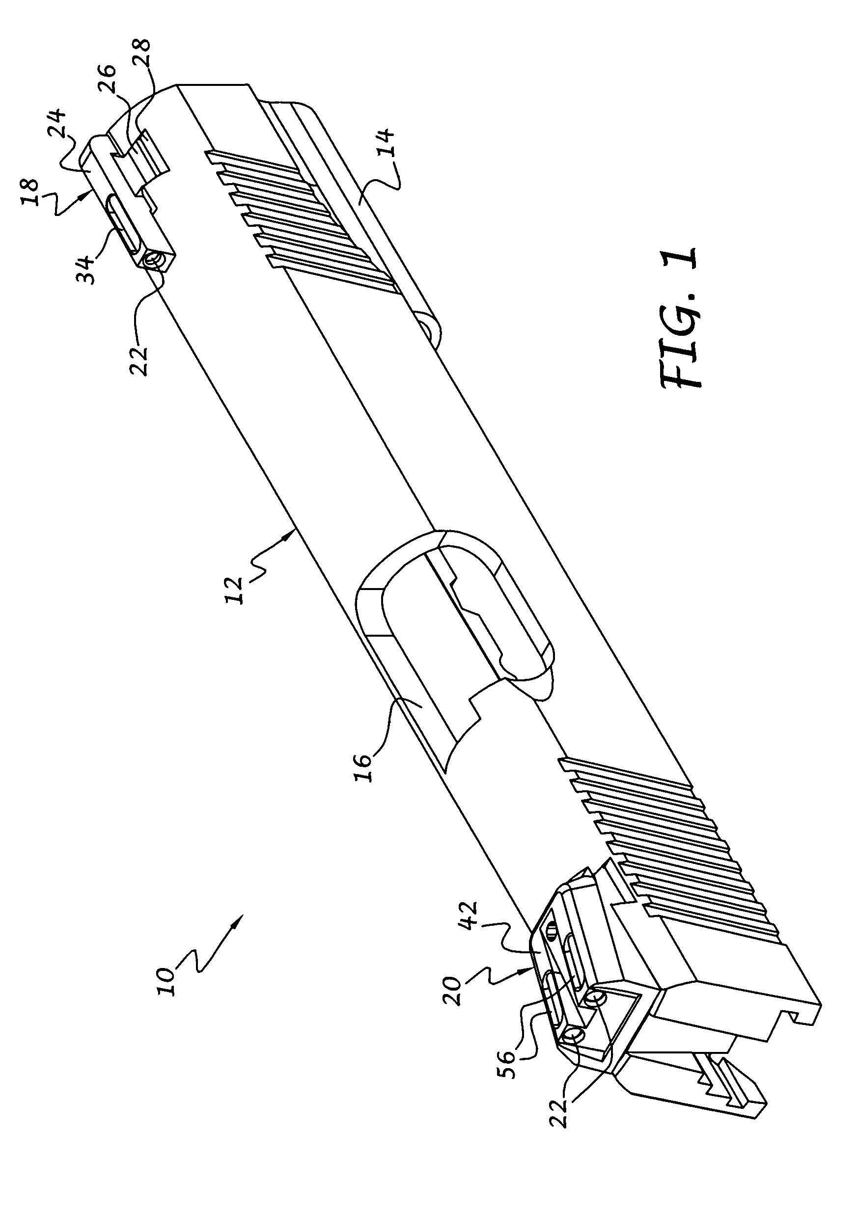
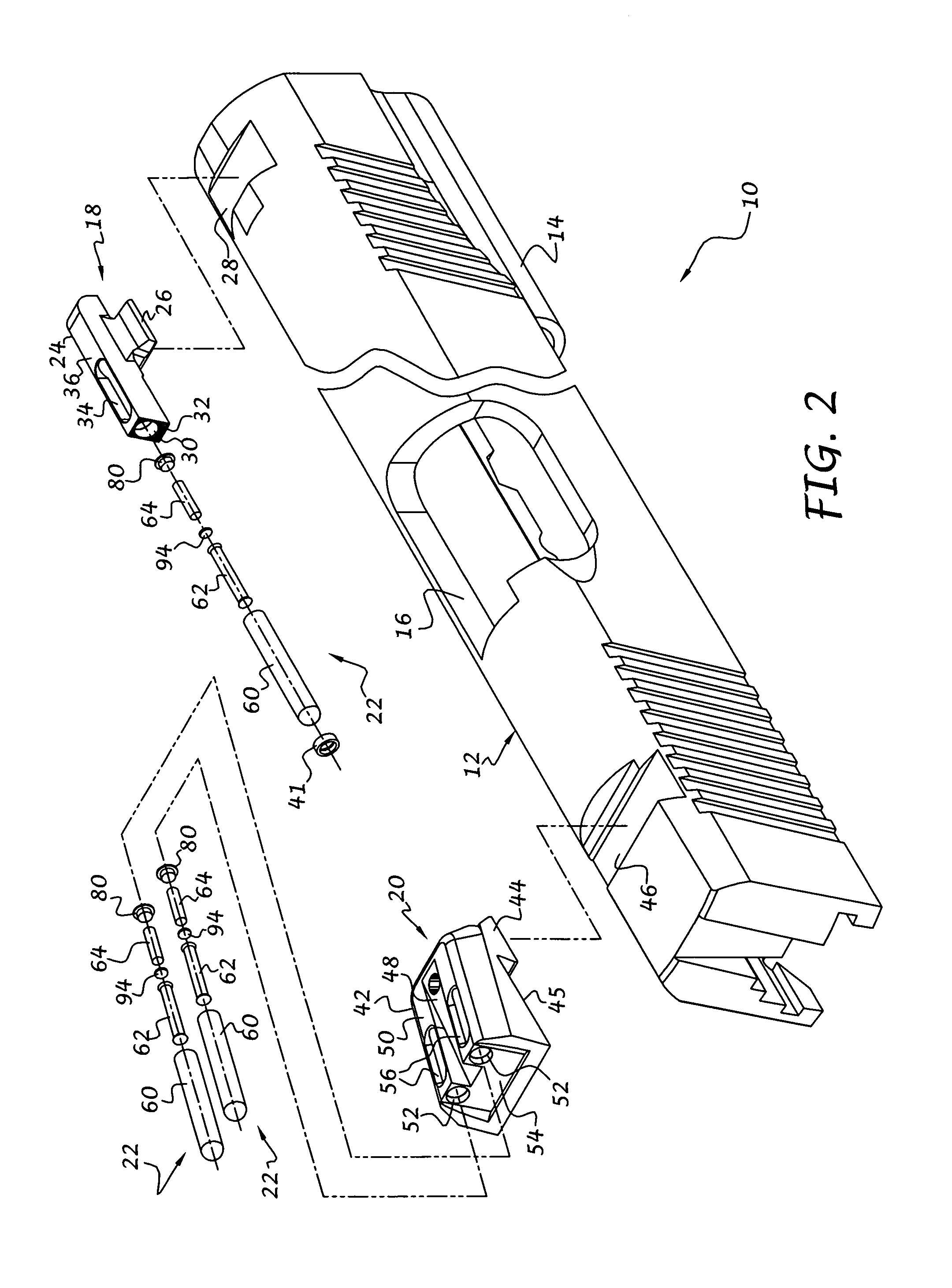
[0021]Referring to the drawings, and to FIGS. 1 and 2 in particular, a sight assembly 10 in accordance with the present invention is illustrated. The sight assembly 10 can be adapted for use with a particular projectile launching device (not shown) such as a handgun, rifle, pellet gun, BB gun, bow, or the like. As illustrated, and by way of example only, the sight assembly 10 may include a mounting base 12 that is slidably mounted to a handgun (not shown), with a barrel-receiving tube 14, an opening 16 for accommodating cartridges ejected from the handgun, a front sight module 18 and a rear sight module 20 positioned at forward and rearward ends, respectively, of the mounting base 12. Each sight module preferably includes one or more illuminated sighting devices 22 that serve as sight points or dots for aligning the projectile launching device with a distal target.

[0022]With additional reference to FIGS. 3, 4 and 7, the front sight module 18 preferably includes a front base member 2...


PUM


Abstract

An illuminated sighting device includes a capsule with an integrally formed lens that is adapted to face rearwardly for viewing by a user. An elongate light collector is positioned within the hollow interior of the capsule and is formed such that light can be gathered along its length and transmitted to its ends. One of the light collector ends is located adjacent to the first lens and defines a sight point or dot. An artificial light source is located within the capsule hollow interior and is oriented for projecting radiant energy into the second light collector end so that the sight point is viewable during dark or low light conditions.

Description

BACKGROUND OF THE INVENTION[0001]This invention relates generally to sighting devices for firearms, archery bows, or other projectile launching devices, and more particularly to a self-illuminated sighting device having both a light collector, such as a fluorescent-doped fiber optic, and an artificial light source for illuminating the light collector in low light or dark conditions.[0002]Sighting devices using short segments of light gathering fiber optics, such as scintillating or fluorescent-doped fiber optics, are currently in use. Such fiber optics gather ambient light along their length and transmit that light to their ends. Under ideal lighting conditions, one end of the fiber optic typically serves as a bright aiming point, the brightness being directly dependent on the level of ambient light incident on the length of fiber optic. However, the short segments of fiber optic have a limited light gathering ability. Under very low lighting conditions, such as at late dusk or earl...

Claims


Application Information

Patent Timeline
Patent Type & Authority Patents(United States)
IPC IPC(8): F41G1/32
CPCF41G1/345
Inventor LOROCCO, PAUL
Owner GOOD SPORTSMAN MARKETING LLC
Why Eureka
Try Eureka