Fixed torque preload piece

a torque preload and torque technology, applied in the field of ball screw, can solve the problems of affecting the precision of the mechanism, affecting the accuracy of the mechanism, and still some problems to be solved

Active Publication Date: 2009-07-21
HIWIN TECH
View PDF7 Cites 5 Cited by
  • Summary
  • Abstract
  • Description
  • Claims
  • Application Information

AI Technical Summary

Benefits of technology

[0017]The primary objective of the present invention is to provide a fixed torque preload piece that can produce preload and can absorb suddenly increased pressure.
[0018]The preload piece of the present invention is installed between two nuts of a ball screw, the preload piece and the two nuts can be radially positioned by inserting clamp plates in keyslots. The preload piece utilizes adjusting members, elastic members and adjusting screws to make the steel balls perform pushing action, and the steel balls in the through holes will be pushed against the two nuts by the arc-shaped abutting surface of the adjusting member, the pushing of the steel balls can produce an adjustable preload, can absorb the sudden increase of the pressure effectively.
[0019]The secondary objective of the present invention is to provide a fixed torque preload piece that can reduce its own rigidity while maintain strong support and preventing deformation.
[0020]The preload piece and the two nuts is radially positioned by inserting clamp plates in keyslots, the pushing force of the steel balls produced by the cooperation between the adjusting members and the elastic members will reduce the rigidity of the preload (improving the flexibility). The steel balls and the elastic members can absorb the sudden increase of pressure, and the preload piece and the clamp plates provide strong enough support (prevention of overly deformation). Therefore, the present invention can reduce the rigidity of the preload piece while preventing deformation of the structure and preventing overly abrasion of the nuts and the screw shaft.
[0021]The third objective of the present invention is to provide a fixed torque preload piece that can adjust the preload as desired.
[0022]An adjusting member, an elastic member and an adjusting screw are installed in each of the threaded holes sequentially, the steel balls in the through holes are pushed against the two nuts by the arc-shaped abutting surface of the adjusting member, the rise and fall of the adjusting members can change the abutting force of the steel balls, thus obtaining a function of easily adjusting the preload at any time.

Problems solved by technology

Therefore, there are still some problems to be solved.
Such change in thread pith will cause instability when the steel balls are rolling between the nut and the screw shaft, and the preload subjected on the linear product itself will become uneven, causing output fluctuation (decrease in precision of the mechanism) and overly abrasion (preload will go off gradually).
First, the thickness of the preload piece is difficult to control.
The repeating grinding work is very troublesome, and if the preload piece is not replaced periodically, the preload will go off.
However, this rigidity of this conventional preload is too great, it will be unable to absorb sudden increase in preload, on the contrary, it will cause deformation of the element.
First, the elasticity and the thickness of preload leaf spring 12 are difficult to control, to control the preload value and to solve the abrasion of the preload leaf spring 12, the preload leaf spring 12 must be replaced periodically or grinded constantly.
Second, the flimsy leaf spring 12 generates a preload for pushing the two nuts 10 outward, however, if the rigidity of the preload leaf spring is not great enough, or if the sudden increase of the preload is too large, the screw shaft 11 and the two nuts 10 will likely be damaged.
These two opposite preload leaf springs automatically adjust the preload and absorb the deformation force between the two nuts, however they still have the following problems:
Second, on the outer periphery of the two nuts 14 is arranged the annular positioning assembly 17, and the annular positioning assembly 17 has too many components and is complicated in structure, this will cause a substantial increase in assembly and maintenance cost.

Method used


Image

  • Fixed torque preload piece
  • Fixed torque preload piece
  • Fixed torque preload piece

Examples


Embodiment Construction

[0033]The foregoing, and additional objects, features and advantages of the present invention will become apparent from the following detailed description of preferred embodiments thereof, taken in conjunction with the accompanying FIGS. 3-7.

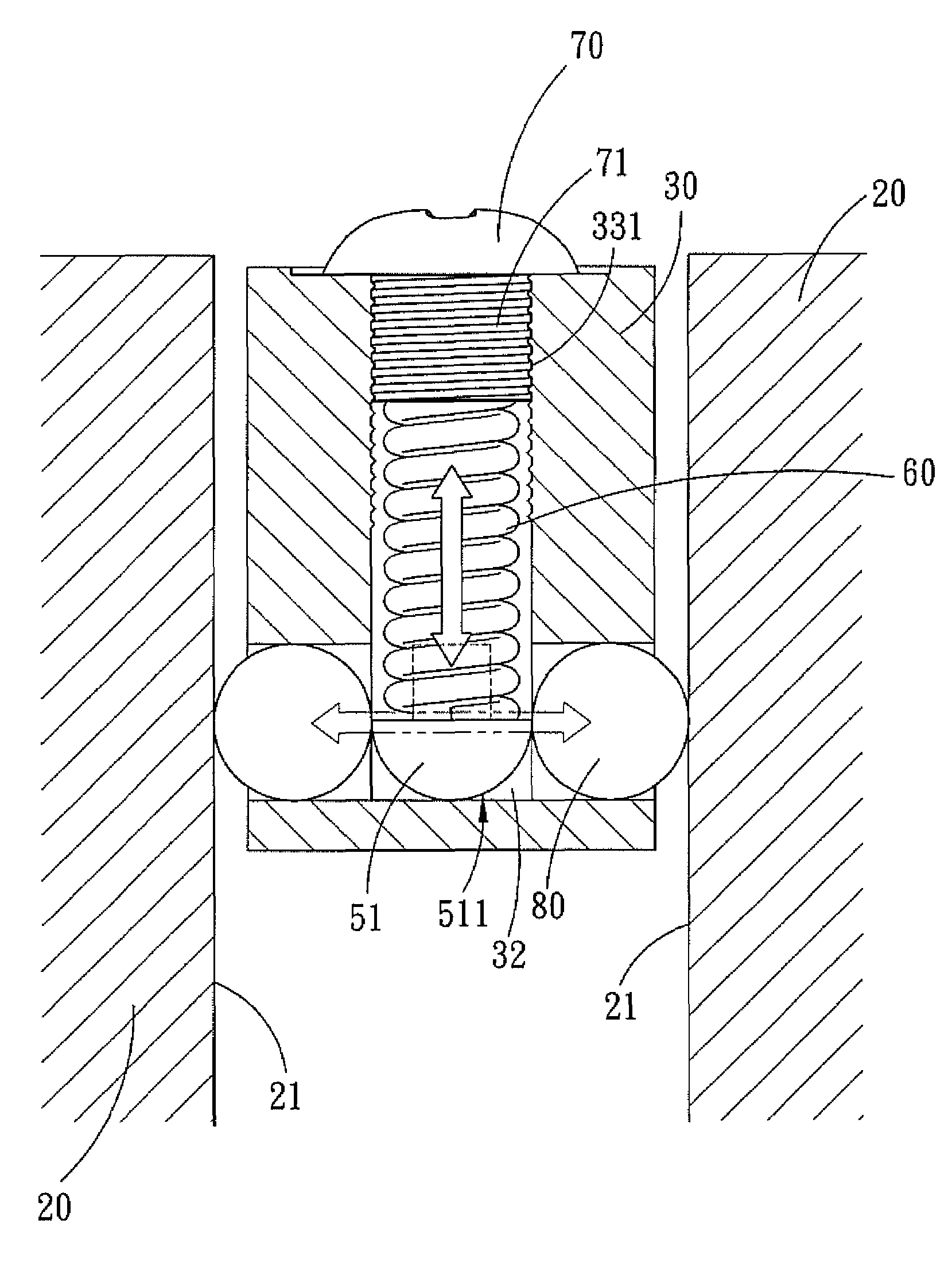
[0034]The structure of a first embodiment of the present invention comprises two nuts 20, preload piece 30, two clamp plates 40, three adjusting members 50, three elastic members 60, three adjusting screws 70 and six steel balls 80 that are arranged outside a ball screw (not shown), and its structure is explained as follows:

[0035]The two nuts 20 are oppositely screwed on the screw shaft with their opposite surfaces 21 facing each other, and a plurality keyslots 22 are formed at corresponding positions in a periphery of each of the opposite surfaces 21 of two nuts 20.

[0036]The preload piece 30 is installed between the two nuts 20, and the preload piece 30 is an annular structure formed by two semicircular pieces. A plurality of keyslots 31 are fo...


PUM


Abstract

A fixed torque preload piece is positioned between two nuts of a ball screw, the preload piece is formed with through hole located in an axial direction of the two nuts for receiving at least two steel balls. Two terminal openings of each of the through holes are defined in the surfaces of the preload piece facing the two opposite nuts. Three radial threaded holes are formed in the outer periphery of the preload piece, and the threaded holes are vertical to and in communication with the through holes. An adjusting member, an elastic member and an adjusting screw are received sequentially in the respective threaded holes. The steel balls in the through holes are pushed against the two nuts by the arc-shaped abutting surface of the adjusting member, the pushing of the steel balls can produce an adjustable preload, and can absorb the sudden increase of the pressure effectively, thus obtaining the objective of the present invention of outputting torque stably.

Description

BACKGROUND OF THE INVENTION[0001]1. Field of the Invention[0002]The present invention relates to a ball screw, and more particularly to a fixed torque preload piece that is located between two nuts of the ball screw, its design can reduce the rigidity of the preload piece and prevent deformation, and the pushing motion of the steel balls can generate an adjustable preload and can effectively absorb the sudden increase of pressure.[0003]2. Description of the Prior Art[0004]Nowadays, with the advancement of various precision feeding system, various linear motion mechanisms have widely come into human life, manufacturing factory and high science and technology instruments, such as linear guideway, ball screw, and the like. Although the technology for linear mechanism is developing fast, consumers still need the technology to be improved constantly. Therefore, there are still some problems to be solved. And this desire for constant improvement of technology is particular strong in many ...

Claims


Application Information

Patent Timeline
Patent Type & Authority Patents(United States)
IPC IPC(8): F16H29/20
CPCF16H25/2209Y10T74/18728
Inventor CHEN, XIN-HE
Owner HIWIN TECH
Why Eureka
Try Eureka