Worm wheel and electric power steering system

a technology of electric power steering and worm wheels, which is applied in the direction of gearing, transportation and packaging, hoisting equipment, etc., can solve the problems of driving discomfort, and achieve the effect of increasing the connection strength between the rim portion and the core portion and superior durability

Inactive Publication Date: 2009-07-21
JTEKT CORP
View PDF10 Cites 8 Cited by
  • Summary
  • Abstract
  • Description
  • Claims
  • Application Information

AI Technical Summary

Benefits of technology

[0014]Further, according to the invention, the connecting strength between the rim portion and the core portion can be increased further. In particular, a risk that the annular flange rides on the outer circumference of the core portion can be eliminated in an ensured fashion.
[0015]With an electric power steering system for assisting in steering by transmitting power of an electric motor to a steering mechanism via a transmission gear which incorporates the worm wheel according to the invention, even in the event that the output of the electric power steering system is increased, the electric power steering system can still provide the superior durability.

Problems solved by technology

When these sounds are transmitted into the passenger compartment as noises, the driver is rendered uncomfortableness.

Method used


Image

  • Worm wheel and electric power steering system
  • Worm wheel and electric power steering system
  • Worm wheel and electric power steering system

Examples


example

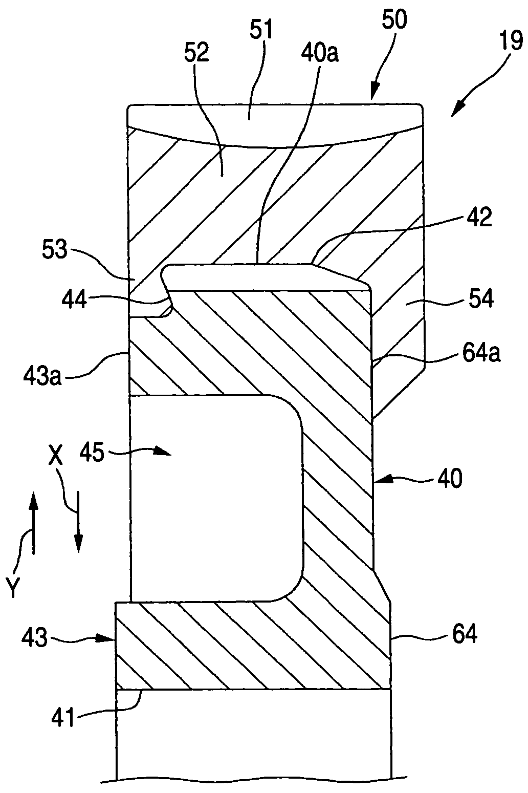
[0053]A worm wheel according to the embodiment was prepared which is identical in shape to the worm wheel shown in FIG. 3. PA66 was used for the rim portion, and the gear module was made to be 1.65 and 55 teeth were formed (the reduction ratio was made to be 18.33). In addition, referring to FIG. 4, the thickness T of the first annular flange 53 was made to be 2.8 mm, and the width W thereof was made to be 3.65 mm, the undercut amount D being made to be 1.33 mm.

[0054]On the other hand, a worm wheel was prepared as a comparison example which differs from the embodiment worm wheel only in that the bottom portion 44a of the recess 44 in FIG. 3 was made to have a perpendicular surface relative to the axis of the core portion 40 to thereby delete the undercut portion.

[0055]As a result of the measurement of the maximum transmissible torque (corresponding to the tooth root strength) of each of the embodiment and comparison example worm wheels under the environment of a high temperature of ...


PUM


Abstract

A worm wheel includes an annular metallic core portion and a resin rim portion which is fitted on an outer circumference of the core portion. The rim portion includes an annular main body portion which covers the outer circumference of the core portion and in which a toothed portion is formed on an outer circumference thereof and a pair of annular flanges which are made to extend from the main body portion in a radially inward direction X to thereby cover, respectively, outer edge portions of first and second sides of the core portion. The first annular flange 53 engages with a recess formed in the corresponding side of the core portion. A bottom portion of the recess includes an undercut portion in relation to a radially outward direction.

Description

BACKGROUND OF THE INVENTION[0001]The present invention relates to a worm wheel and an electric power steering system including the worm wheel.[0002]A speed reduction gear is used in an automotive electric power-steering system (EPS). For example, in a column-type EPS, the rotational force of a motor is transmitted to a worm and then to a worm wheel, whereby the rotational speed of the motor is reduced so as to amplify the output of the motor to thereby assist with torque for steering operation.[0003]Incidentally, while an appropriate backlash is necessary for mesh engagement between the worm and the worm wheel, when driven on, for example, a rough road such as a road paved with stones or bricks, a beating sound attributed to the backlash may be generated by virtue of reaction from tires, or a rattling sound may be generated from bearings and other components having plays. When these sounds are transmitted into the passenger compartment as noises, the driver is rendered uncomfortable...

Claims


Application Information

Patent Timeline
Patent Type & Authority Patents(United States)
IPC IPC(8): F16H1/16B62D5/04F16H55/06
CPCB62D5/0409F16H55/06Y10S74/10Y10T74/19921Y10T74/19828Y10T74/19907B62D5/04
Inventor KUROKAWA, TAKANORIMATSUBARA, HIDEOSHIINA, AKIHIKO
Owner JTEKT CORP
Why Eureka
Try Eureka