Treadmill with cushion assembly

a cushion and treadmill technology, applied in the field of treadmills, can solve the problems of high impact load on the user's feet, ankles and knees, unnecessary damage to joints, etc., and achieve the effect of reducing high impact load

Inactive Publication Date: 2009-07-21
JOHNSON HEALTH TECH
View PDF22 Cites 37 Cited by
  • Summary
  • Abstract
  • Description
  • Claims
  • Application Information

AI Technical Summary

Benefits of technology

[0005]The present invention provides a treadmill including a frame adapted to be supported on a floor surface, an endless belt having an upwardly-exposed exercise section, a deck disposed between the exercise section of the belt and the frame and a cushion assembly positioned between the deck and the frame for providing cushion in order to reduce high impact loads on the user's feet, ankles and knees. The cushion assembly comprises a lever having a first portion that is adapted to be rotated and a second portion that is rotatably coupled to the frame wherein the first portion of the lever is operably coupled to the deck. The cushion assembly also comprises a resilient member operably coupled to the lever and the frame wherein the resilient member resists rotation of the lever as the lever is being rotated. The elastic deformation of the resilient member could provide resistance to displacement of the deck and therefore create a cushion effect on the user's feet, ankles and knees as the user's feet contact the belt and the deck.

Problems solved by technology

Therefore, decks are commonly relatively rigid, which can result in high impact loads on the user's feet, ankles and knees as the user's feet contact the belt.
These high impact loads are uncomfortable and further can result in unnecessary damage to joints as compared to running on a softer surface.
While generally successful at reducing impact loads, these approaches have certain disadvantages.

Method used


Image

  • Treadmill with cushion assembly
  • Treadmill with cushion assembly
  • Treadmill with cushion assembly

Examples


Embodiment Construction

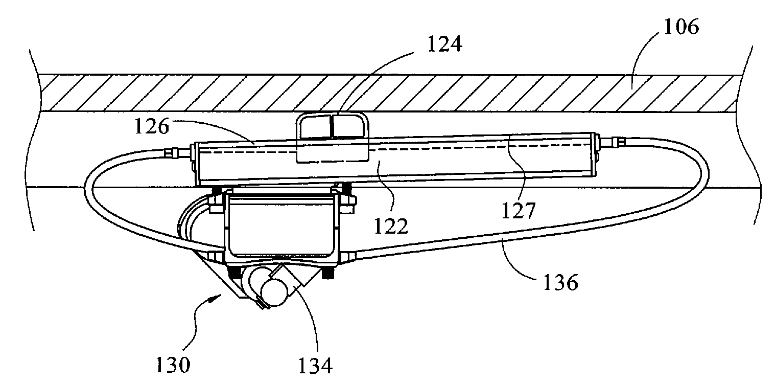
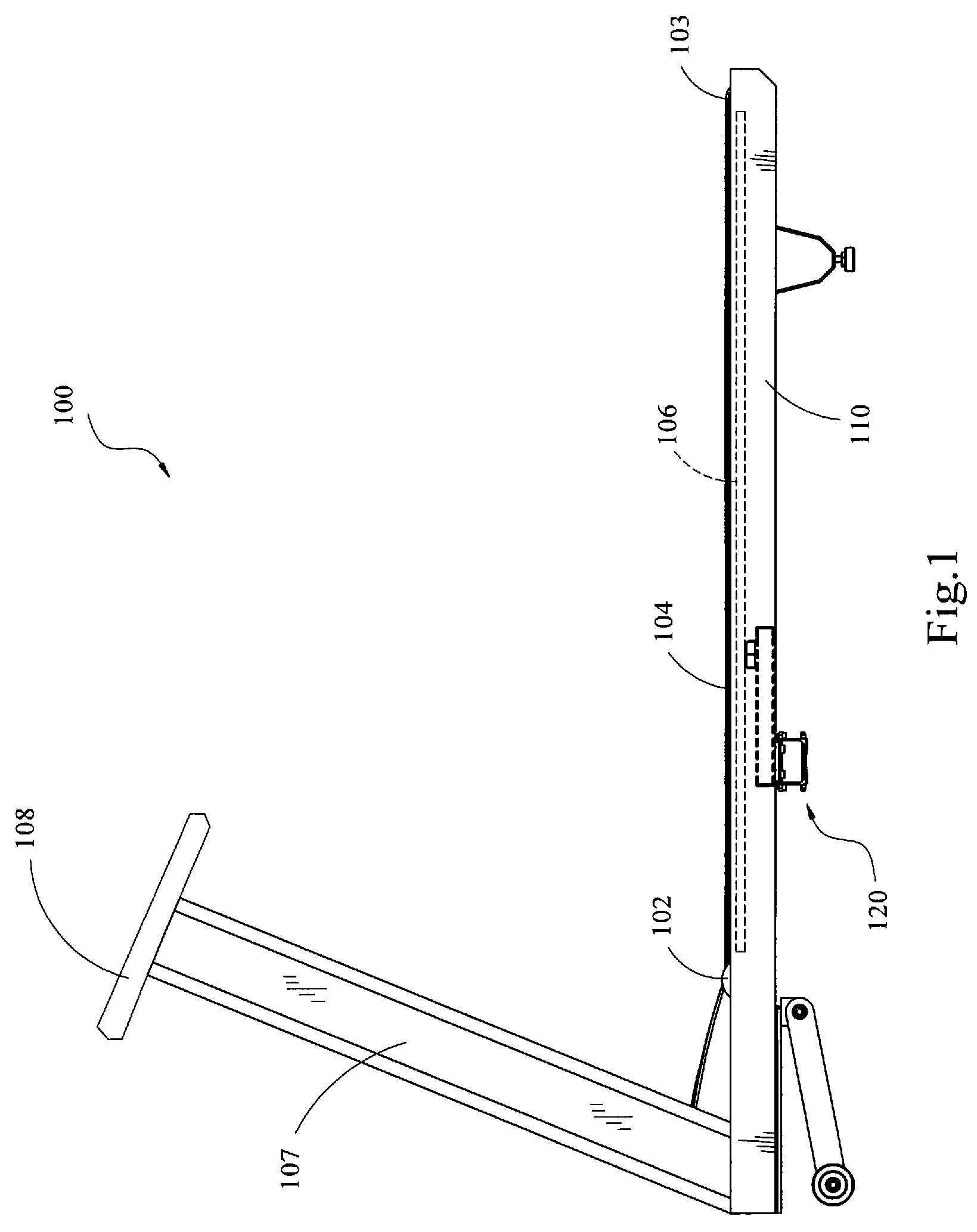
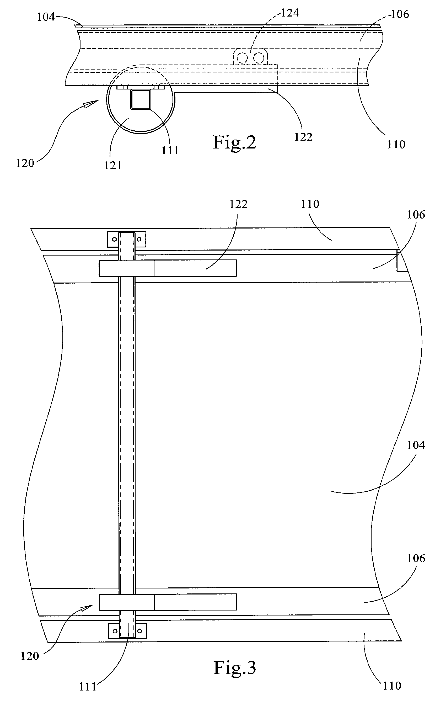
[0027]FIG. 1 illustrates a treadmill 100 with a cushion assembly 120 for providing cushion to a user as the user walks or runs on the treadmill 100. The treadmill 100 comprises a frame 110 adapted to rest on a floor surface. A forward roller 102 and a rear roller 103 are spaced and journalled in the frame 110. An endless belt 104 is trained on the rollers 102,103. The belt 104 has an upwardly-exposed exercise section extending longitudinally between the rollers 102, 103 and adapted to enable a user to exercise thereon. A console support 107 extends upward from the frame 110 and terminates with a console 108. The console 108 generally is for displaying information to a user of the treadmill 100 and allowing the user to select parameters of operating the treadmill 100 as the user desires. The rollers 102 and 103 are driven by an electronic motor (not shown), and the transmitting speed of the exercise section of the endless belt 104 is controlled by a user via the console 108.

[0028]A l...


PUM


Abstract

A treadmill including a frame, an endless belt having an upwardly-exposed exercise section, a deck disposed underneath the exercise section of the belt, and a cushion assembly positioned between the deck and the frame for providing cushion in order to reduce high impact loads on the user's body. The cushion assembly comprises a lever having a first portion that is operably coupled to the deck and a second portion that is rotatably coupled to the frame. The cushion assembly also comprises a resilient member coupled to both the lever and the frame so that the resilient member resists rotation of the lever as the lever is rotated. The elastic deformation of the resilient member provides resistance to displacement of the deck and therefore creates a cushion effect on the user's feet, ankles and knees as the user's feet contact the belt.

Description

BACKGROUND OF THE INVENTION[0001]The present invention relates to a treadmill and, more particularly, to a treadmill with a cushion assembly.[0002]Indoor exercise is getting more and more popular during recent decades. One popular indoor exercise apparatus is the treadmill. Treadmills commonly include a frame supported on the floor surface, and a console support extending upward from a front end of the frame. Two rollers are positioned at opposite ends of the frame, and an endless belt is trained on the rollers. A deck is positioned under the endless belt. A user may step on the endless belt for walking, running or other exercise purpose.[0003]The upper portion of the belt is typically supported by the deck beneath the upper surface of the belt. The deck is usually composed of wood in order to provide the required support. Therefore, decks are commonly relatively rigid, which can result in high impact loads on the user's feet, ankles and knees as the user's feet contact the belt. Th...

Claims


Application Information

Patent Timeline
Patent Type & Authority Patents(United States)
IPC IPC(8): A63B22/02
CPCA63B22/0235A63B24/00A63B2022/0228A63B2022/0221Y10S482/908A63B22/0228A63B22/0221
Inventor ALLING, JON C.
Owner JOHNSON HEALTH TECH
Why Eureka
Try Eureka