Container including object-supporting chute and pivot mechanism

a technology of object support and chute, which is applied in the direction of container/bottle construction, large containers, packaging, etc., can solve the problems of not being able to carry other than cylindrical cargo items, and the container is not useful for continued transportation, so as to avoid damage to the cargo, improve the friction of cylindrical objects, and reduce the mass centre

Active Publication Date: 2016-06-28
OY LANGH SHIP AB
View PDF17 Cites 5 Cited by
  • Summary
  • Abstract
  • Description
  • Claims
  • Application Information

AI Technical Summary

Benefits of technology

[0003]An object of the invention is to provide a new container which is easily modifiable to be adapted to carry cylindrical cargo items or, alternatively, in principle any other cargo. The container allows a cylindrical cargo item to be carried to its destination and in principle any cargo on the way back —or vice versa. The container even enables both cylindrical cargo items and other cargo to be carried at the same time.
[0005]There is preferably a first pivot at a tip of a wedge-shaped support member and a second pivot close to the top edge of the lower wall zone, below the surface of the lower wall zone. This type of arrangement enables the support member to be dimensioned in such a manner that a distance between the lower wall zone and the upper wall zone, i.e. a transition area, can be made small and the chute as uniform as possible without a wide interfering transition or discontinuation when the support member is in a first position of use and serves as the upper wall zone of the chute.
[0006]Both sides at the respective ends of the support member are preferably provided with a pivot mechanism because this type of pivoting increases the solidity of the structure.
[0008]The container preferably comprises a multitude of support members at a distance from one another, with pivot mechanisms at both ends of the pieces, the ends of the support members being also preferably formed as stopping means for preventing cylindrical objects from sliding in a longitudinal direction of the chute. Because of the multitude of support members, the container offers a wide variety of modification options, and the weight of the support members remains relatively low which makes the support members easy to turn manually. It is recommended to prevent reels and rolls from sliding in the chute, because sliding causes high impact loads on the structures. When a support member is turned down, its side serves as a means of stopping a reel or a roll. A risk of reels sliding and moving arises when the container is subject to high acceleration forces during transport.
[0010]Major advantages of the container of the invention are its suitability for various uses and extreme ease of modification according to need: it is suitable for carrying not only round cargo items but also other types of load. Moreover, when heavy reels are transported, the mass centre is low. The pivot mechanism with two pivots and a pivoting arm connecting them enables a uniform chute to be formed in which the pivot mechanism does not protrude from the chute. Such a protrusion would be in the way during loading or transport and thus prone to damage. In addition, the pivot mechanism allows the chute to be provided with a friction-increasing material with the aim of improving friction against cylindrical objects to be carried and avoiding damage to the cargo, without the friction-increasing material causing high loads to the pivot mechanism when the container is used for transporting other than cylindrical objects and when the support members are turned into a position in which they and the horizontal support plane together form a uniform loading plane.

Problems solved by technology

A problem with this prior art container is that it is not suitable for carrying other than cylindrical cargo items.
When used for carrying a cylindrical item from point A to point B, the cylindrical item being unloaded in point B, the container is not useful for the continued transport unless other cylindrical objects are to be carried from point B. As a result, the container returning from point B is typically empty until reloaded again in point A (or some other point) with cylindrical cargo items.

Method used


Image

  • Container including object-supporting chute and pivot mechanism
  • Container including object-supporting chute and pivot mechanism
  • Container including object-supporting chute and pivot mechanism

Examples


Embodiment Construction

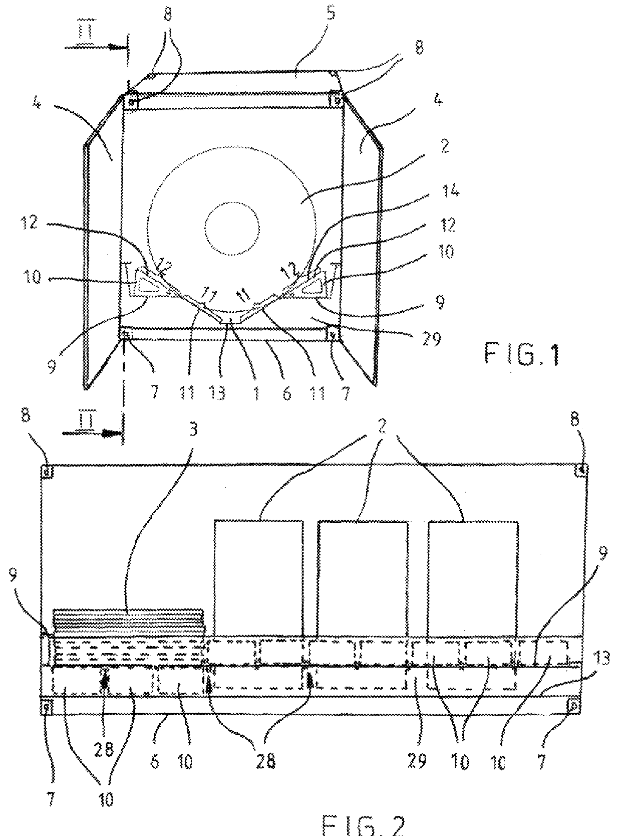
[0019]FIG. 1 is a perspective end view illustrating a container of the invention and FIG. 2 is a side view illustrating the container of FIG. 1 along a section line II-II of FIG. 1. The dimensions of the container correspond to those of a standard container of 20 feet. Hence the width of the container is 8 feet and the height of the container is approximately 8.5 feet.

[0020]The container comprises a chute 1 in a longitudinal direction thereof, with three reels 2 loaded in the chute. The reels are steel reels, but they could be paper reels or other cylindrical objects, such as tubes. At one end of the container there is a plate load 3 (see FIG. 2). An operating mechanism included in the container allows a desired length to be chosen for the chute 1. In FIG. 2 the length of the chute 1 has been set equal to about three reels, the chute being filled close to one end thereof with wedge-like support members 10 belonging to the operating mechanism. The structure and operation of the suppo...


PUM


Abstract

A container includes a chute for supporting reels, the chute including a bottom, a lower wall zone, an upper wall zone, and a support frame for supporting the chute. The container has a horizontal support plane on both sides of the chute, the upper wall zone being formed by a first support surface of a wedge-like support member placed onto the support plane, a second support surface of the support member resting against the support plane when the support member is in a first use position; a pivot mechanism allowing the support member to be turned in relation to the support frame so that the first support surface sets against the lower wall zone of the chute and the second support surface sets onto the same height level as the support plane for forming a uniform loading plane and for placing the support member to a second use position.

Description

BACKGROUND OF THE INVENTION[0001]The invention relates to a container comprising a chute for supporting cylindrical objects, such as reels and tubes, the chute comprising a bottom and a wall structure that extends upward and outward from the bottom of the chute on both sides thereof and is bipartite on both sides of the chute, comprising a lower wall zone and an upper wall zone as an extension of the lower wall zone, and a support frame for supporting the chute.[0002]This type of container is known from publication WO 2009 / 118459 A1. A problem with this prior art container is that it is not suitable for carrying other than cylindrical cargo items. When used for carrying a cylindrical item from point A to point B, the cylindrical item being unloaded in point B, the container is not useful for the continued transport unless other cylindrical objects are to be carried from point B. As a result, the container returning from point B is typically empty until reloaded again in point A (or ...

Claims


Application Information

Patent Timeline
Patent Type & Authority Patents(United States)
IPC IPC(8): B65D25/10B65D90/00B65D85/02
CPCB65D25/103B65D85/02B65D90/006B65D2590/0058B65D19/44B65D85/04B65D88/12B65D90/00
Inventor LANGH-LAGERLOF, LAURA
Owner OY LANGH SHIP AB
Why Eureka
Try Eureka